Optical film and a liquid crystal display using the same

a liquid crystal display and optical film technology, applied in the field of optical film and liquid crystal display using the same, can solve the problems of insufficient improvement of the components at the backlight (e.g., light-transmission plates and cfls) to achieve the brightness required in the lcds, and the use of collimating film is required

Inactive Publication Date: 2003-04-17
NITTO DENKO CORP
View PDF6 Cites 93 Cited by
  • Summary
  • Abstract
  • Description
  • Claims
  • Application Information

AI Technical Summary

Problems solved by technology

Since LDPs become larger and enhanced in brightness, improvement of the components at the backlights (e.g., light-transmission plates and CFLs) are not sufficient for securing brightness required in the LCDs.
However, sinc...

Method used


Image

  • Optical film and a liquid crystal display using the same
  • Optical film and a liquid crystal display using the same
  • Optical film and a liquid crystal display using the same

Examples


examples

[0053] The present invention will be described below more specifically by referring to Examples and Comparative Examples, though the present invention is not limited to the Examples.

[0054] In the Examples, the brightness enhancement film was prepared as described below by laminating a cholesteric liquid crystal layer, a .lambda. / 4 plate, and absorption dichroic polarizing plate in this order.

example of

production of a brightness enhancement film

[0055] A polyvinyl alcohol oriented film having a thickness of 0.1 .mu.m was formed on a triacetylcellulose (TAC) film having a thickness of 50 .mu.m. Subsequent to a rubbing treatment, cholesteric liquid crystal polymers, being 700 nm, 550 nm, and 400 nm in the central wavelengths of selective reflection, were formed successively in three layers on the oriented film. The respective layers had a thickness of about 3 .mu.m. A .lambda. / 4 plate made of polycarbonate and 60 .mu.m in thickness was adhered to this cholesteric liquid crystal layer by using an acrylic pressure-sensitive adhesive. Iodine-based polarizing plates (having acrylic pressure-sensitive adhesive layers formed on both surfaces thereof were attached to the plate by aligning the transmission axis so as to obtain a brightness enhancement film.

[0056] Although not specifically mentioned in this example, it is preferable that the prism shape of the collimating film is optimized de...

example 1

[0065] A die having a prism pattern with a point angle of 45.degree. and a 50 .mu.m pitch was prepared. Separately, a brightness enhancement film made of triacetylcellulose (TAC) having a multi-layered cholesteric liquid crystal polymer film was prepared in accordance with the above-described method. Acrylic resin 8 .mu.m in thickness was coated on a surface of the brightness enhancement film, i.e., a surface opposite to the multi-layered film. Then, the pattern was heat-transferred with heat-pressing by using the die so as to obtain a brightness enhancement film having a light-condensing function.

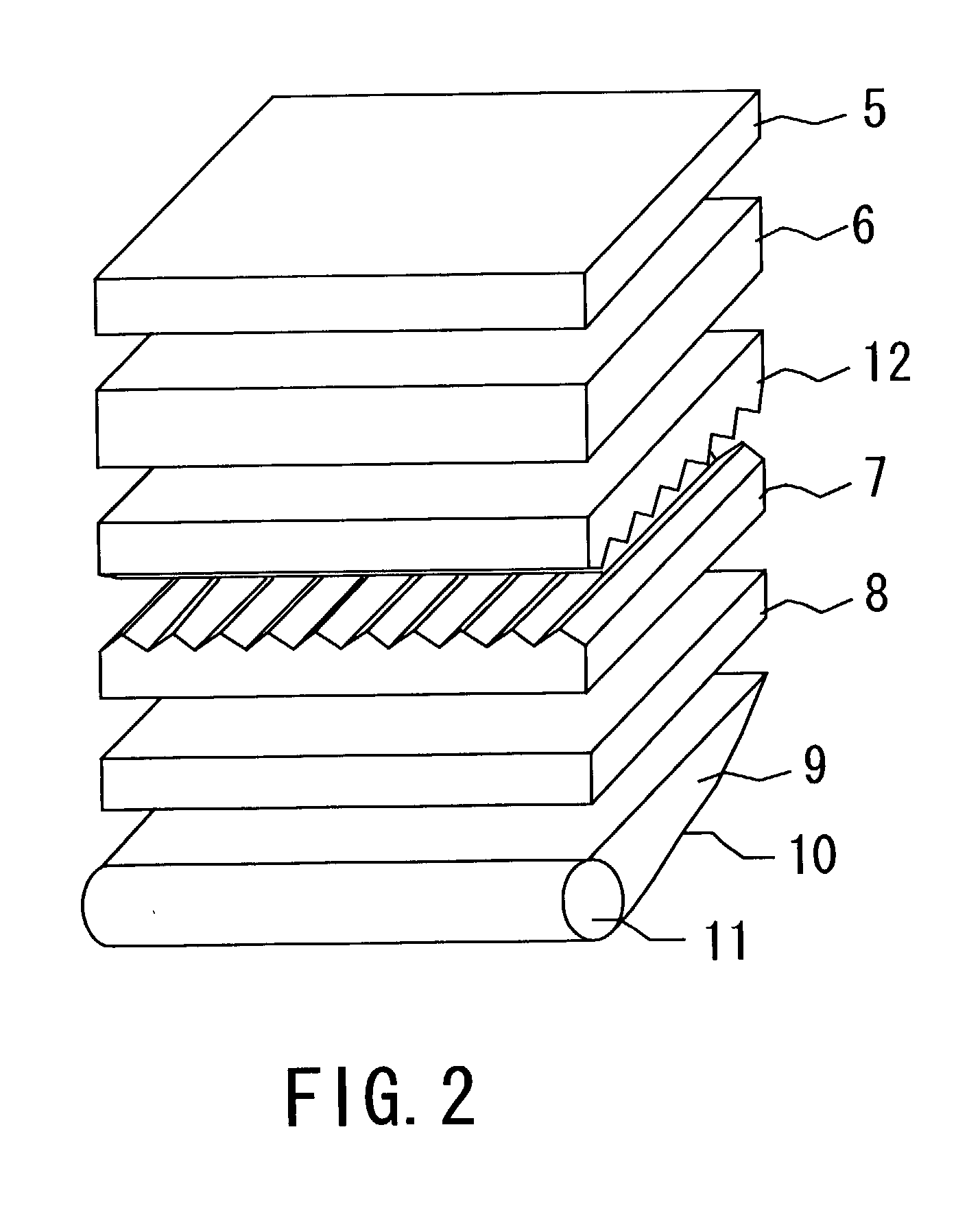
[0066] A diffusion plate (8) made of an acrylic resin was mounted on a light-transmission plate (9) made of polymethylmethacrylate. A sheet of collimating film (7) made of acrylic resin was mounted thereon. A brightness enhancement film (12) of the present invention, having a light-condensing function, was superposed on the film so as to obtain a liquid crystal display as shown in FIG. 2. ...


PUM


Abstract

An optical film having excellent light utilization efficiency and high brightness, and a liquid crystal display using the optical film. The optical film is formed by laminating integrally a brightness enhancement film (A) that separates natural light into transmitted light and reflected light and a collimating film (B) having an uneven portion on a surface thereof. Since an air interface is eliminated by the integral lamination of the brightness enhancement film and the collimating film, stray light is reduced, and the brightness enhancement film has an improved efficiency in reflecting and polarizing light; thereby, enhancing the brightness.

Description

[0001] The present invention relates to an optical film that can efficiently utilize light and achieve high brightness, and a liquid crystal display using the optical film.PRIOR ART[0002] Due to the advantages provided by the characteristics such as reduction in the thickness and weight and the lowered power consumption, liquid crystal displays (LDCs) are used widely as flat panel displays indispensable in the era of highly developed information and communications and the applications thereof are increasing year after year. More particularly, with the 21.sup.st century coming close, uses of large type LCDs (such as, monitor cameras or televisions) have increased remarkably. Under these circumstances, characteristics required for the current LCDs include: 1) high brightness, 2) wide visual angle, 3) fast response, and 4) high definition. Among them, the high brightness is particularly required. Brightness of a typical laptop type personal computer (PC), which was from 70 cd / m.sup.2 t...

Claims


Application Information

Patent Timeline
IPC IPC(8): F21V8/00G02B6/00G02F1/13357G02F1/13363
CPCG02B6/0046G02B6/005G02B6/0053G02F2001/133638G02B6/0071G02F1/13362G02F2001/133543G02B6/0068G02F1/133543G02F1/133638
Inventor SHIRAOGAWA, MIKIMOTOMURA, HIRONORIKAWAMOTO, IKUO
Owner NITTO DENKO CORP
Why Eureka
Try Eureka