Thermal interface material and electronic assembly having such a thermal interface material

Inactive Publication Date: 2003-04-24
INTEL CORP
View PDF3 Cites 125 Cited by
  • Summary
  • Abstract
  • Description
  • Claims
  • Application Information

AI Technical Summary

Problems solved by technology

Such a die may have solder bump contacts on the integrated circuit.
Operation of the integrated circuit causes heating thereof.
However, the thermally conductive grease has only a moderate thermal conductivity and thus provides a substantial thermal barrier for heat transferring from the die to the heat spreader.

Method used


Image

  • Thermal interface material and electronic assembly having such a thermal interface material
  • Thermal interface material and electronic assembly having such a thermal interface material
  • Thermal interface material and electronic assembly having such a thermal interface material

Examples


Embodiment Construction

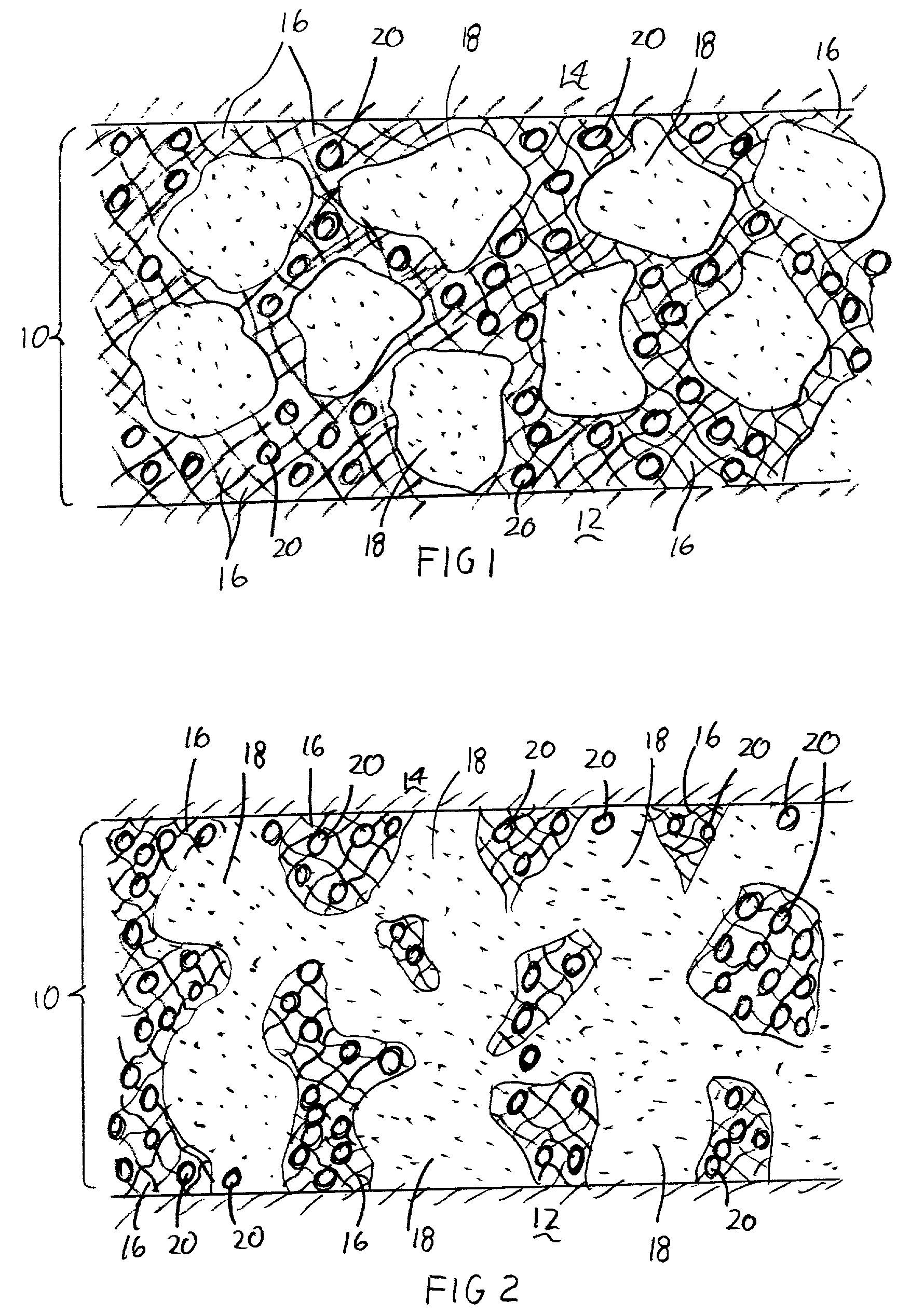
[0027] An example of the thermal interface material 10 is now given.

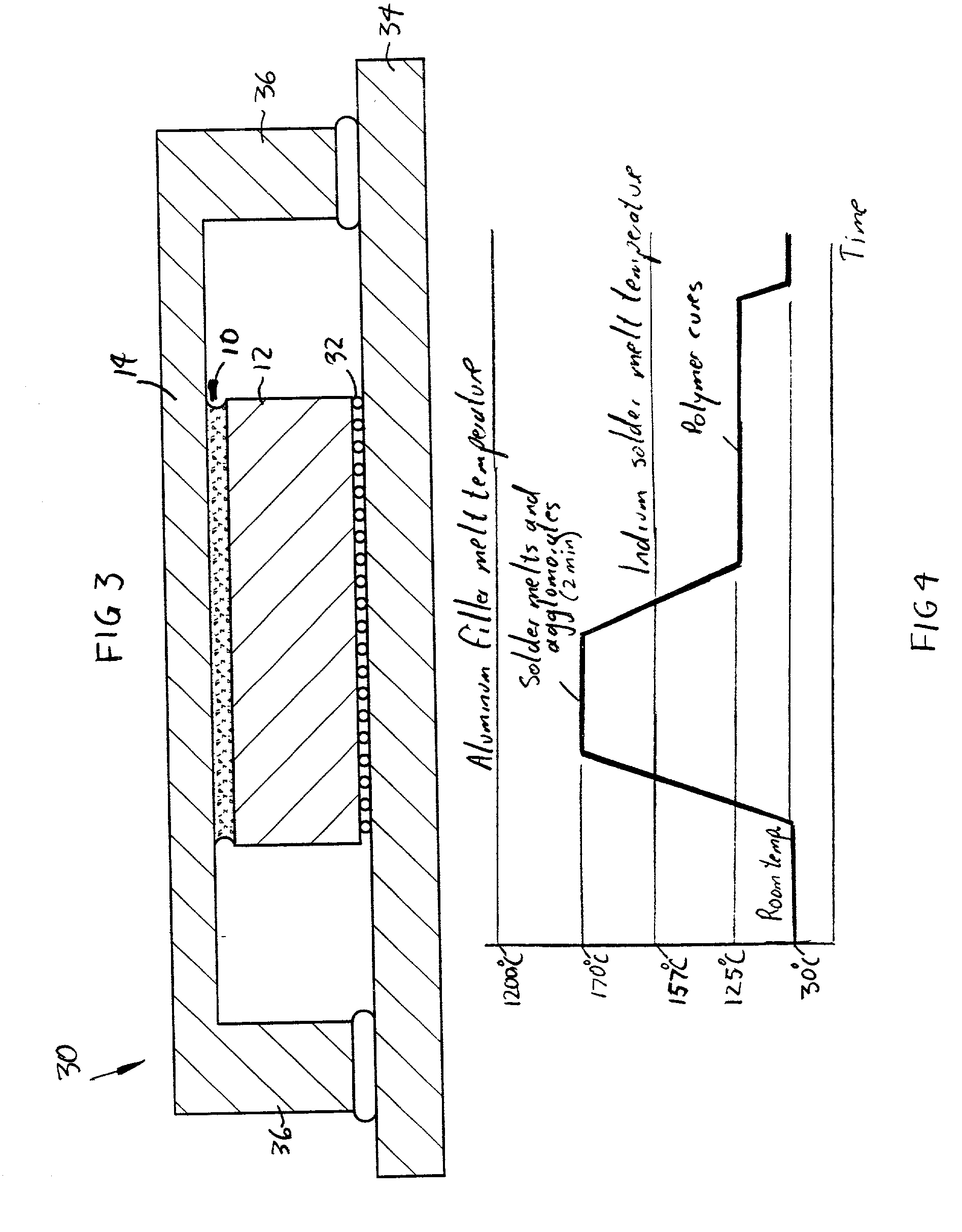
[0028] The matrix material 16 is silicone comprising 8% of the thermal interface material 10 by weight. The solder material 18 is indium comprising 77% of the thermal interface material 10 by weight. Indium has a melting temperature of 157.degree. C. and does not attack silicone when melted at a temperature above 157.degree. C. The filler particles 20 are made of aluminum comprising 15% of the thermal interface material 10 by weight. The solder particles 18 and the filler particles 20 thus comprise approximately 92% of the thermal interface material 10 by weight. Aluminum has a melting temperature of approximately 1200.degree. C. The filler particles 20 thus melt at a temperature which is 1043.degree. C. higher than the melting temperature of the solder particles 18.

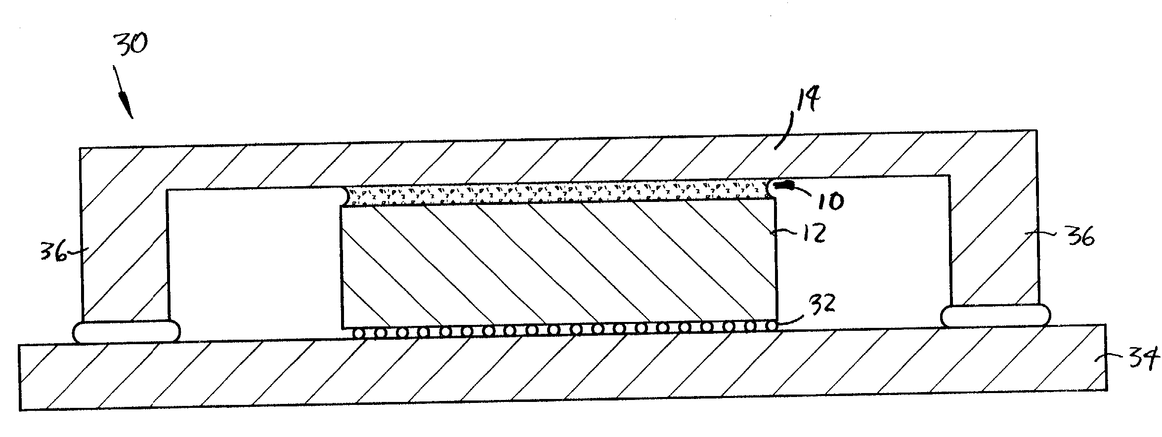
[0029] Heat is generated by the die 12 and transferred through the solder particles 18 to the thermally conductive member 14. Differences in thermal exp...


PUM

PropertyMeasurementUnit
melting temperatureaaaaaaaaaa

Abstract

A thermal interface material is described for thermal coupling of an electronic component to a thermally conductive member. The thermal interface material includes a viscoelastic polymer matrix material, fusible solder particles in the matrix material, and filler particles in the matrix material. The solder particles have a melting temperature below a selected temperature (e.g. 157° C. for indium) and the filler particles have a melting temperature substantially above the selected temperature (e.g. 961° C. for silver). The filler particles keep the thermal interface material intact under adverse thermal and stress conditions.

Description

[0001] 1). Field of the Invention[0002] This invention relates to a thermal interface material for thermal coupling of an electronic component to a thermally conductive member, and to an electronic assembly which has such a thermal interface material.[0003] 2). Discussion of Related Art[0004] Integrated circuits are manufactured on semiconductor wafers, which are subsequently sawed or "diced" into individual dice. Such a die may have solder bump contacts on the integrated circuit. The solder bump contacts are located downwardly onto contact pads of a package substrate. Electronic signals can be provided through the solder bump contacts to and from the integrated circuit.[0005] Operation of the integrated circuit causes heating thereof. Heat is conducted to an upper surface of such the die and has to be conducted or convected away to maintain the temperature of the integrated circuit below a predetermined level for the purpose of maintaining functional integrity of the integrated cir...

Claims


Application Information

Patent Timeline
Patent Type & Authority Applications(United States)
IPC IPC(8): H01L23/373H01L23/42
CPCH01L23/3737Y10T428/256H01L24/29H01L2224/16225H01L2224/73253H01L2924/01005H01L2924/01013H01L2924/01029H01L2924/01033H01L2924/0104H01L2924/01047H01L2924/01049H01L2924/0105H01L2924/01058H01L2924/01322H01L2924/14H01L2924/16152H01L2924/0132H01L2924/0133H01L2924/0135H01L2924/0134H01L2224/29H01L2224/2919H01L2924/01006H01L2924/014H01L2924/0665H01L2224/29101H01L2224/29109H01L2224/29111H01L2924/0001H01L2224/29324H01L2224/2929H01L2224/29309H01L2224/29311H01L2224/29339H01L2224/29347H01L2224/29355H01L2224/29386H01L2224/29393Y10S428/913H01L2924/00013H01L2224/16227H01L2224/32245Y10T428/25Y10T428/252Y10T428/12896Y10T428/2982Y10T428/1225Y10T428/257Y10T428/12701Y10T428/258H01L23/42H01L2924/00H01L2924/01022H01L2924/01034H01L2924/01083H01L2924/00014H01L2924/0503H01L2924/05032H01L2924/04642H01L2924/05432H01L2224/29099H01L2224/29199H01L2224/29299Y10T428/31511Y10T428/31529Y10T428/31663Y10T428/31692
Inventor DANI, ASHAY A.KONING, PAUL A.JAYARAMAN, SAIKUMARRUMER, CHRISTOPHER L.
Owner INTEL CORP
Why Eureka
Try Eureka