
Rocket motors with insensitive munitions systems

a technology of insensitive munitions and rocket motors, which is applied in the direction of machines/engines, weapons types, weapons, etc., can solve the problems of excessive pressure, increased hazard to nearby personnel and property, and increased propulsive power of rocket motors before properly aimed, so as to reduce overall inert weight, increase the range and effect of rocket motors

Inactive Publication Date: 2003-05-01
NORTHROP GRUMMAN SYST CORP
View PDF0 Cites 8 Cited by
  • Summary
  • Abstract
  • Description
  • Claims
  • Application Information

AI Technical Summary

Benefits of technology

[0024] It is another object of this invention to address the above-advancement by providing a gun-launched rocket motor designed to diminish the net loads that the rocket motor case experiences during gun launch, reduce the inert weight and increase the available propellant volume, and provide an insensitive munitions case and closure design.
[0032] In accordance with this third aspect of the invention, the interior environment controlled movable piston accommodates volume changes due to propellant thermal expansion and accommodates the substantial gun pressures associated with gun launched projectiles. This enables a rocket motor structure design with the ability to withstand a dramatic rapid rise and dramatic sudden fall in pressure associated with gun launched rockets. The movable piston also permits the rocket motor to be constructed from thinner and lighter materials to increase the available propellant volume and reduce overall inert weight. As a consequence, the range and effectiveness of the rocket motor are increased. Simultaneously, the rocket motor incorporates IM capability to permit the rocket motor to be rendered relatively harmless should the solid propellant inappropriately ignite while being stored or transported.

Problems solved by technology

During pre-launch storage, when a rocket motor is ignited inadvertently by external heating, such as a spilled fuel fire, the rocket motor may become propulsive before being properly aimed.
When inadvertent ignition is caused by fragment impact that produces unplanned nozzle outlets, the motor may become wildly propulsive in undesired directions.
And when such events produce unplanned increases of propellant burning surface area, excessive pressurization may increase the hazard to nearby personnel and property.
One problem associated with many of these conventional IM systems is that they do not pass slow cook off tests.
For many conventional IM systems, heating at relatively slow rates of about 6.degree. F. / hr causes the entire propellant to combust substantially instantaneously prior to activation of the IM systems, producing excess gas which the IM systems are not equipped to handle and safely expel.
Unless the configuration and support arrangement allow deformations to occur, thermal stresses in the propellant may cause fractures, undesired increases of burning surface area, and disasters upon ignition.
The threat that gun accelerations may pose to the integrity of a propellant charge may be great unless care is exercised over the propellant configuration and means of supporting the propellant.
During gun launch, alternatives to the aft end support arrangement for the propellant grain can be grave threats to the integrity of the propellant grain.
Indeed, at acceleration levels typical of gun launches, neither the bonded circumferential surface of an axially perforated propellant grain nor an unperforated grain with a bonded forward end is stiff enough to eliminate the aft end support mode unless there is a great deal of empty space within the motor.
This threatens to buckle the case if the duration of the lag is large enough.
However, the outside diameter, and hence the available volume for propellant, of gun-launched rocket motors is limited by the size of the gun bore from which the rocket motors are fired.
This may require thicker structures which diminish the volume available for propellant, and which increase the inert weight of the motor, thereby diminishing the attainable range or velocity of the projectile.

Method used


Image

  • Rocket motors with insensitive munitions systems
  • Rocket motors with insensitive munitions systems
  • Rocket motors with insensitive munitions systems

Examples


Embodiment Construction

[0042] Reference will now be made in detail to the presently preferred embodiments and methods of the invention as described below. It should be noted, however, that the invention in its broader aspects is not limited to the specific details, representative devices and methods, and examples described in this section in connection with the preferred embodiments and methods. The invention according to its various aspects is particularly pointed out and distinctly claimed in the attached claims read in view of this specification, and appropriate equivalents.

[0043] It is to be noted that, as used in the specification and the appended claims, the singular forms "a," "an," and "the" include plural referents unless the context clearly dictates otherwise.

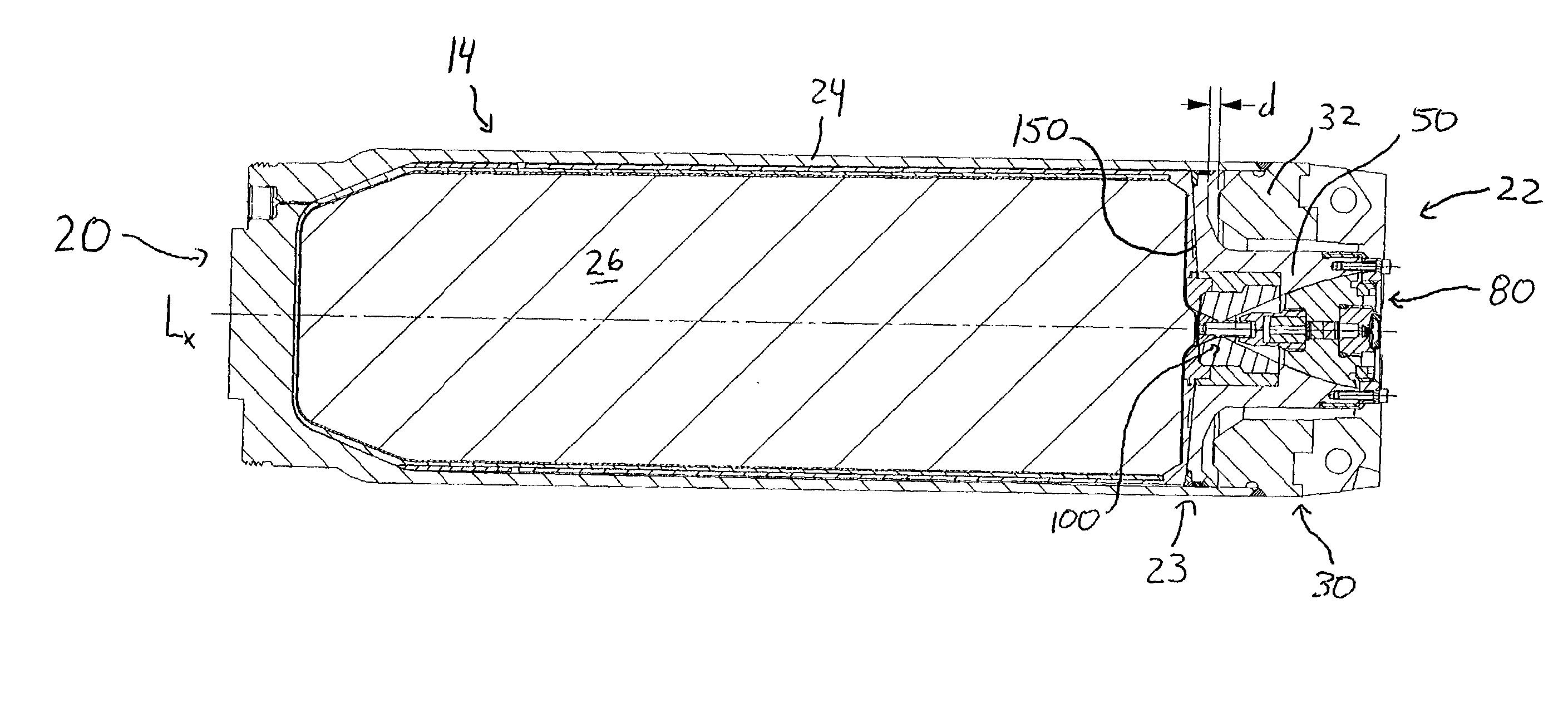
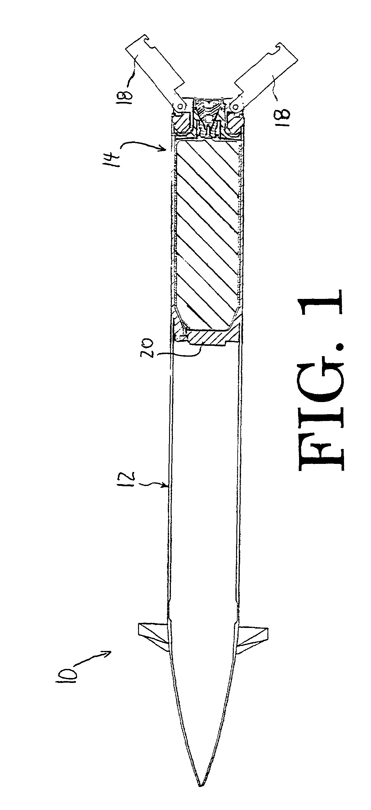
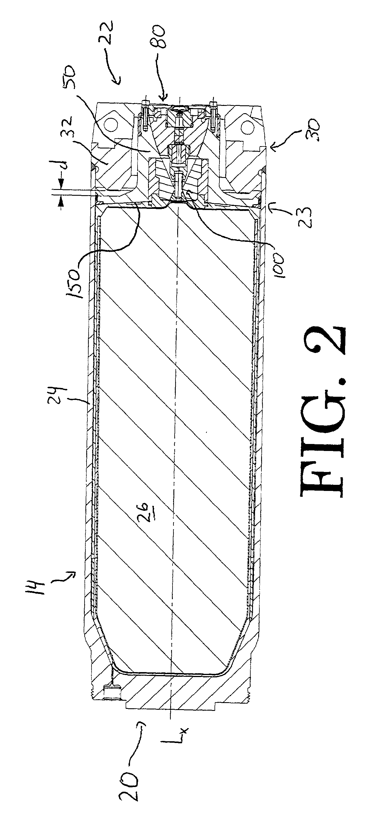
[0044] FIG. 1 shows a projectile, generally designated by reference numeral 10, that includes a forward end 12 that can contain some payload, such as, for example, a guidance system and / or an explosive charge, and an aft rocket motor, gener...


PUM


Abstract

An embodiment of the rocket motor of this invention employs an insensitive munitions approach that, when subjected to elevated external temperatures, is activated by thermal expansion of the main propellant and gas generation from a secondary insensitive munitions charge. In a preferred embodiment, the rocket motor also includes a pressure equalizing system that accommodates changing temperature conditions during storage as well as varying gas pressure inherent in gun-launched systems in a manner that allows for thinner case cylinder design and increased propellant volume.

Description

[0001] 1. The Field of the Invention[0002] The present invention relates to rocket motors, especially for gun-launched projectiles, having insensitive munitions systems.[0003] 2. Description of the Related Art[0004] Many launchable projectiles, rockets, and rocket stages comprise a forward end, including guidance and munitions, and an aft end rocket motor. These two elements can be formed together, with a common outer case, or they can be separately formed and subsequently joined together. This joining can occur immediately prior to use, in which case the two elements may be separately stored, or the elements can be joined together for storage purposes and be ready for immediate use.[0005] During pre-launch storage, when a rocket motor is ignited inadvertently by external heating, such as a spilled fuel fire, the rocket motor may become propulsive before being properly aimed. When inadvertent ignition is caused by fragment impact that produces unplanned nozzle outlets, the motor may...

Claims


Application Information

Patent Timeline
IPC IPC(8): F02K9/38F42B15/00
CPCF42B15/00F02K9/38
Inventor SOLBERG, MARK A.BLACK, ROBERT E.
Owner NORTHROP GRUMMAN SYST CORP
Learn More