Al technical title is built by PatSnap Al team. It summarizes the technical point description of the patent document.
a technology applied in the field of x-ray and neutron imaging, can solve the problems of limited aperture limited ability of compound refractive lens, and small aperture of absorption aperture r.sub.a
Inactive Publication Date: 2003-05-01
ADELPHI TECH INC
View PDF4 Cites 15 Cited by
Summary
Abstract
Description
Claims
Application Information
AI Technical Summary
This helps you quickly interpret patents by identifying the three key elements:
Problems solved by technology
Method used
Benefits of technology
0029] The invention permits the overcoming of the problem of the compound refractive lenses that are highly limited by their apertures and, hence, by their field of view. The method permits the x-ray or neutron imaging of large objects. The invention permits the fabrication of large area arrays of compound refractive lenses that are capable of imaging large objects with either x-rays or neutrons. The invention also permits the collection, focusing or collimation of x-rays or neutrons from large-area sources. The invention permits the use of very small unit lenses of high radius of curvature, which in turn permits short focal length lens systems.
Problems solved by technology
Unfortunately, the aperture of the compound refractive lens is limited.
However, since lens shape can be made parabolic and the mechanical aperture can be made larger, the absorption aperture r.sub.a is usually the limiting aperture.
Thus the compound refractive lens' apertures are small and limited in their ability to capture the total image or collect most of the flux from sources of neutrons or x-rays.
Method used
Image
Click on the blue label to locate the original text in one second.
Reading with bidirectional positioning of images and text.
Examples
Embodiment Construction
s
[0095] 4.1. Microscope and Telescopes
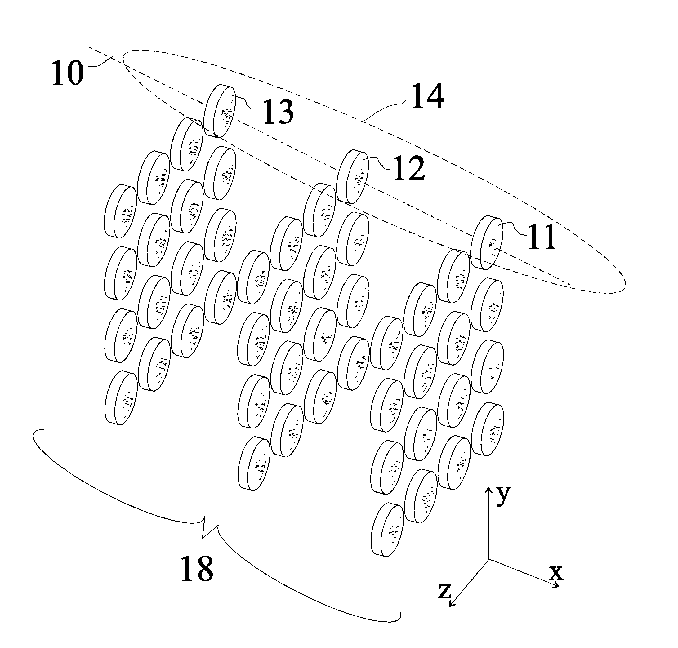
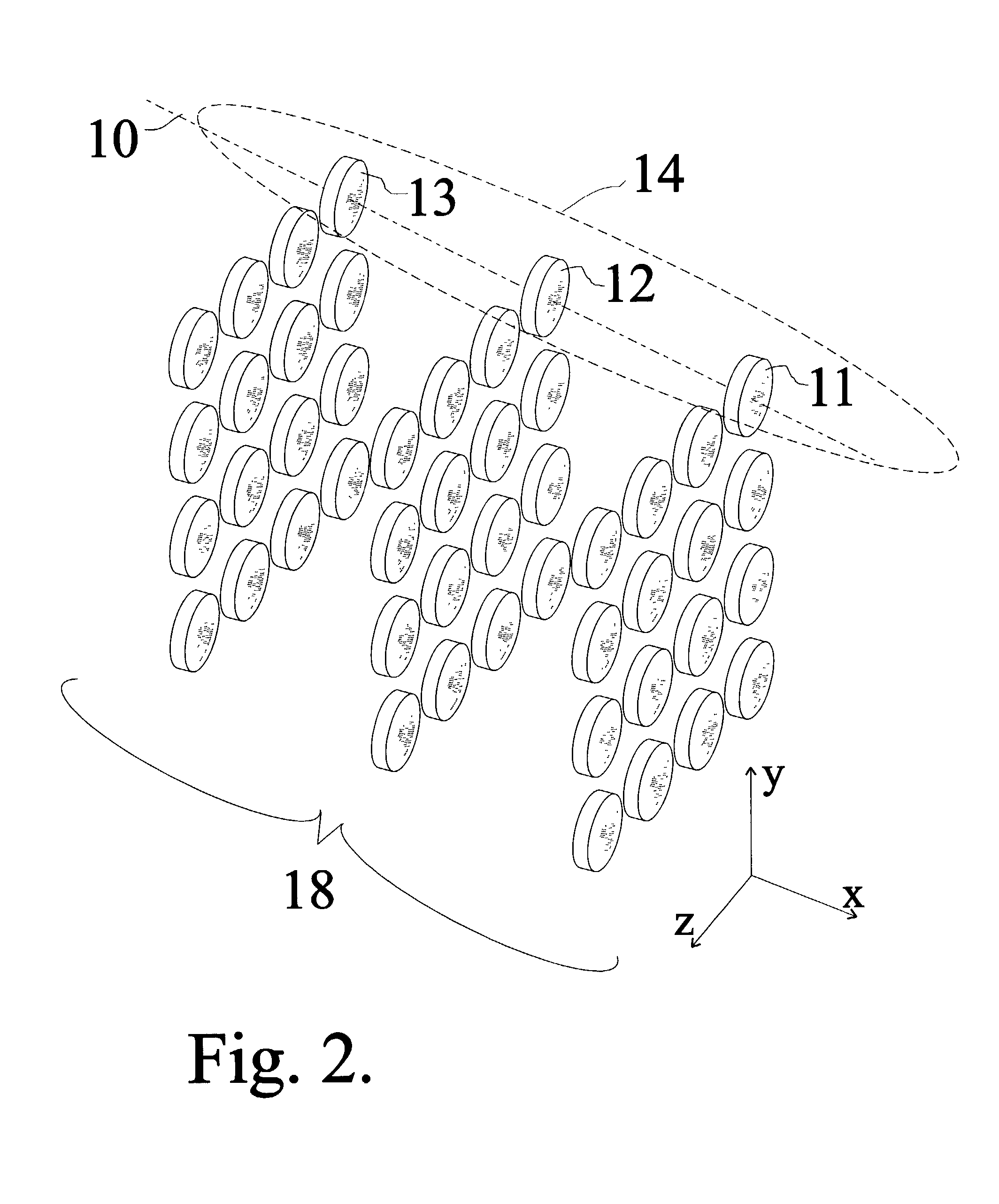
[0096] Using similar systems of 3-D arrays there are many applications using ordinary visible optics, which will now have direct analogies in x-ray and neutron optics systems. X-ray and neutron microscopes having large apertures can now be made, which can magnify small objects embedded in other materials. An x-ray telescope can now be fabricated for the collection and imaging of distant x-ray or neutron emitters. For explosive detection, characteristic-line emission from radioactive sources or from materials whose fluorescent emission has been activated can now be collected, detected and identified from large distances from these sources.
[0097] These embodiments can be used, for example, for x-ray lithography in the production of integrated circuits, and for magnification of breast tissue for the detection of cancer. Medical, industrial, and scientific imaging can be done with these lens arrays. Visible optic analogues from x-ray and neutron app...
PUM
Abstract
An x-ray or neutron apparatus for the transmission of x-ray or neutron images is described, which includes x-ray- or neutron-three-dimensional (3-D) arrays or mosaics, including a plurality of x-ray or neutron lenses positioned so that they form a two-dimensional (2-D) mosaic of compound refractive lenses to provide a plurality of separate x-ray or neutron paths between an object and an image at an x-ray- or neutron-detector. The apparatus is so constructed that it permits separate parts of an object to be imaged such that a total composite image is formed from these various parts. An imaging apparatus of the detection of carcinoma in breast tissue is formed using such an apparatus. Methods of microscopy and imaging are obtained using this apparatus.
Description
U.S. Provisional Patent Documents[0002] Nos. 60 / 322,795 09 / 17 / 2001, M. A. Piestrup, "X-ray and neutron imaging using compound refractive lens arrays."[0003] 60 / 376,677 04 / 29 / 2002, M. A. Piestrup, "X-ray and neutron imaging using compound refractive lens arrays II."[0004] Cross Reference to Related Documents:U.S. Patent Documents[0005] U.S. Pat. No. 6,269,145 B1 May 1998, M. A. Piestrup, R. H. Pantell, J. T. Cremer and H. R. Beguiristain, "Compound Refractive Lens for X-rays," issued: Jul. 31, 2001.[0006] No. RE28,162, R. H. Anderson, "Optical apparatus including a pair of mosaics of optical imaging elements," issued Sep. 17, 1974.[0007] U.S. Pat. No. 5,594,773, Toshihisa Tomie, "X-ray Lens" issued Jan. 14, 1997.[0008] U.S. Pat. No. 5,880,478, D. J. Bishop, L. Gammel, and I. P. M. Platzman, Compound Refractive Lenses for Low Energy Neutrons," issued Mar. 9, 1999.[0009] ______, H. R. Beguiristain, M. A. Piestrup, R. H. Pantell, "Methods of Imaging, Focusing and Conditioning Neutrons,"...
Claims
Application Information
Patent Timeline
Application Date:The date an application was filed.
Publication Date:The date a patent or application was officially published.
First Publication Date:The earliest publication date of a patent with the same application number.
Issue Date:Publication date of the patent grant document.
PCT Entry Date:The Entry date of PCT National Phase.
Estimated Expiry Date:The statutory expiry date of a patent right according to the Patent Law, and it is the longest term of protection that the patent right can achieve without the termination of the patent right due to other reasons(Term extension factor has been taken into account ).
Invalid Date:Actual expiry date is based on effective date or publication date of legal transaction data of invalid patent.
Patent Type & Authority Applications(United States)