Compact combined shift and selective methanation reactor for co control

a methane reactor and combined shift technology, applied in the direction of hydrogen separation using solid contact, physical/chemical process catalysts, chemistry apparatus and processes, etc., can solve the problems of reducing the overall performance of the fuel cell, generating a significant amount of co,

Inactive Publication Date: 2003-05-08
INST OF GAS TECH
View PDF12 Cites 10 Cited by
  • Summary
  • Abstract
  • Description
  • Claims
  • Application Information

AI Technical Summary

Problems solved by technology

However, during the reforming process, a significant amount of CO is also generated which remains in the reformate fuel gas.
The CO, when left in the reformate fuel gas, is absorbed by the plati

Method used


Image

  • Compact combined shift and selective methanation reactor for co control

Examples


Embodiment Construction

[0021] PEM fuel cells operate at 60 to 80.degree. C. and are easily poisoned by high levels of carbon monoxide. Consequently, fuel processors that produce hydrogen-rich fuel gas for PEM fuel cells need to reduce carbon monoxide to low ppm levels. Specifically, carbon monoxide levels of less than about 20 ppm in the fuel cell fuel gases are necessary to attain adequate performance and endurance, even with new developments in mixed platinum-additive catalysts. Currently, to reduce the carbon monoxide level produced by reformers to below 20 ppm, two catalysts in two separate reactor vessels are employed, that is, one for water-gas shift and one for selective methanation of carbon monoxide. In accordance with the method and apparatus of this invention, the two catalysts are loaded into one vessel in a certain sequence of contiguous zones.

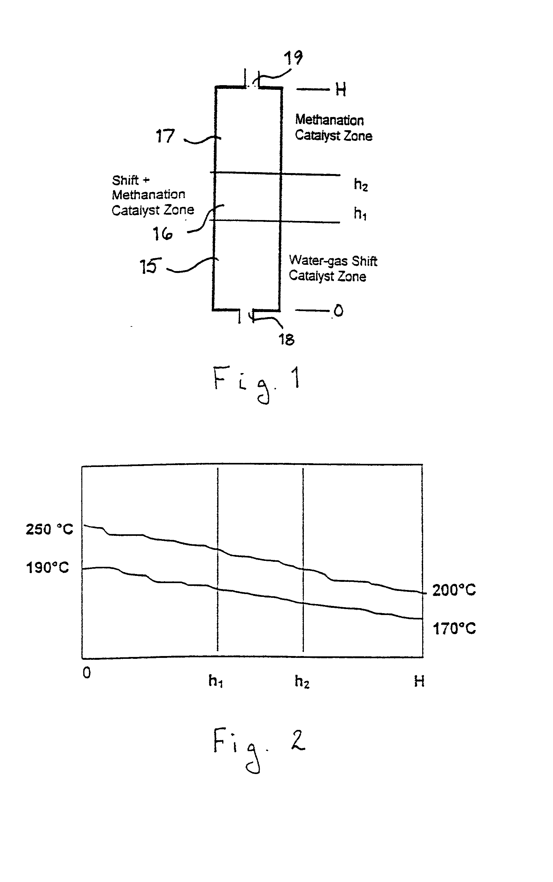
[0022] As shown in FIG. 1, the reactor vessel of this invention comprises a water-gas shift catalyst zone 15, a methanation catalyst zone 17 disposed d...


PUM

PropertyMeasurementUnit
Fractionaaaaaaaaaa
Fractionaaaaaaaaaa
Angleaaaaaaaaaa

Abstract

A reactor for CO control having a reactor vessel having a water-gas shift catalyst zone, a mixed catalyst zone downstream of the water-gas shift catalyst zone, and a methanation catalyst zone disposed downstream of the mixed catalyst zone, at least one water-gas shift catalyst disposed in the water-gas shift catalyst zone, at least one methanation catalyst disposed in the methanation catalyst zone, and a mixture of the water-gas shift catalyst and the methanation disposed in the mixed catalyst zone.

Description

[0001] 1. Field of the Invention[0002] This invention relates to a method and apparatus for controlling the CO content of a reformate fuel gas suitable for use in electrochemical devices for producing electricity, such as polymer electrolyte membrane (PEM) fuel cells. More particularly, this invention relates to a synergistic configuration of a compact and efficient fuel processor for producing a low-carbon monoxide content product gas from a variety of hydrocarbon fuels, including, but not limited to, methane, propane and methanol.[0003] 2. Description of Prior Art[0004] Fuel cells are known apparatuses in which the chemical energy of a fuel is converted directly into electrical energy. Each fuel cell generally includes a pair of electrodes arranged across an electrolyte, wherein the surface of one electrode (the anode) is exposed to a reactive hydrogen-rich fuel gas while the surface of the other electrode (the cathode) is exposed to an oxidizing gas containing oxygen. The electri...

Claims


Application Information

Patent Timeline
IPC IPC(8): B01J8/02B01J8/04C01B3/12C01B3/16C01B3/58
CPCB01J8/0453B01J2208/025C01B3/16C01B3/586C01B2203/0283C01B2203/1076C01B2203/047C01B2203/1047C01B2203/1058C01B2203/107C01B2203/0445
Inventor WANGEROW, JAMES R.SISHTLA, CHAKRAVARTHYHILL, ANDY H.ONISCHAK, MICHAEL
Owner INST OF GAS TECH
Why Eureka
Try Eureka