Array for the contact-less transmission of electrical signals or energy

a contactless transmission and circuit technology, applied in the direction of transmission systems, electric variable regulation, reradiation, etc., can solve the problems of complex and high-cost encapsulation of contact means, reduced efficiency, and reduced efficiency, and achieve the effect of low-loss conversion

Inactive Publication Date: 2003-05-22
SCHLEIFRING & APPBAU
View PDF14 Cites 53 Cited by
  • Summary
  • Abstract
  • Description
  • Claims
  • Application Information

AI Technical Summary

Benefits of technology

0022] In another expedient embodiment of the invention, with at least one receiver, a rectifier with a joining

Problems solved by technology

In order to satisfy such requirements it is necessary to encapsulate the contact means in a complex and high-cost manner.
As a consequence, the structure is substantially changed whilst handling is rendered more difficult.
Specifically with frequent plugging and unplugging cycles, such plug-and-socket connectors present serious disadvantages.
It avoids the principal disadvantage of contacting systems but it entails comparatively high production costs.
This results in very high costs particularly in installations with a high number of contacting means.
Another disadvantage of such ar

Method used


Image

  • Array for the contact-less transmission of electrical signals or energy
  • Array for the contact-less transmission of electrical signals or energy
  • Array for the contact-less transmission of electrical signals or energy

Examples


Embodiment Construction

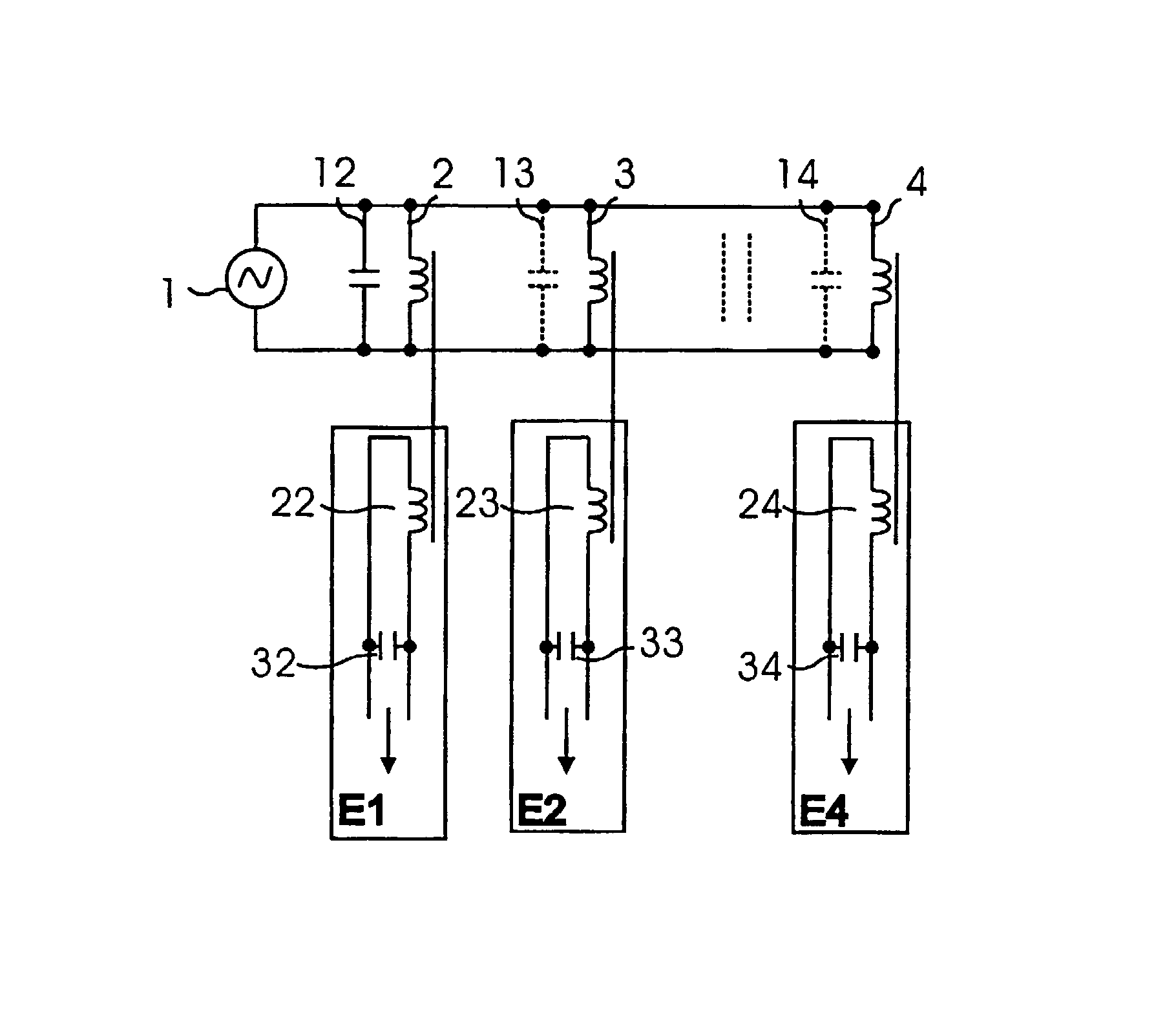
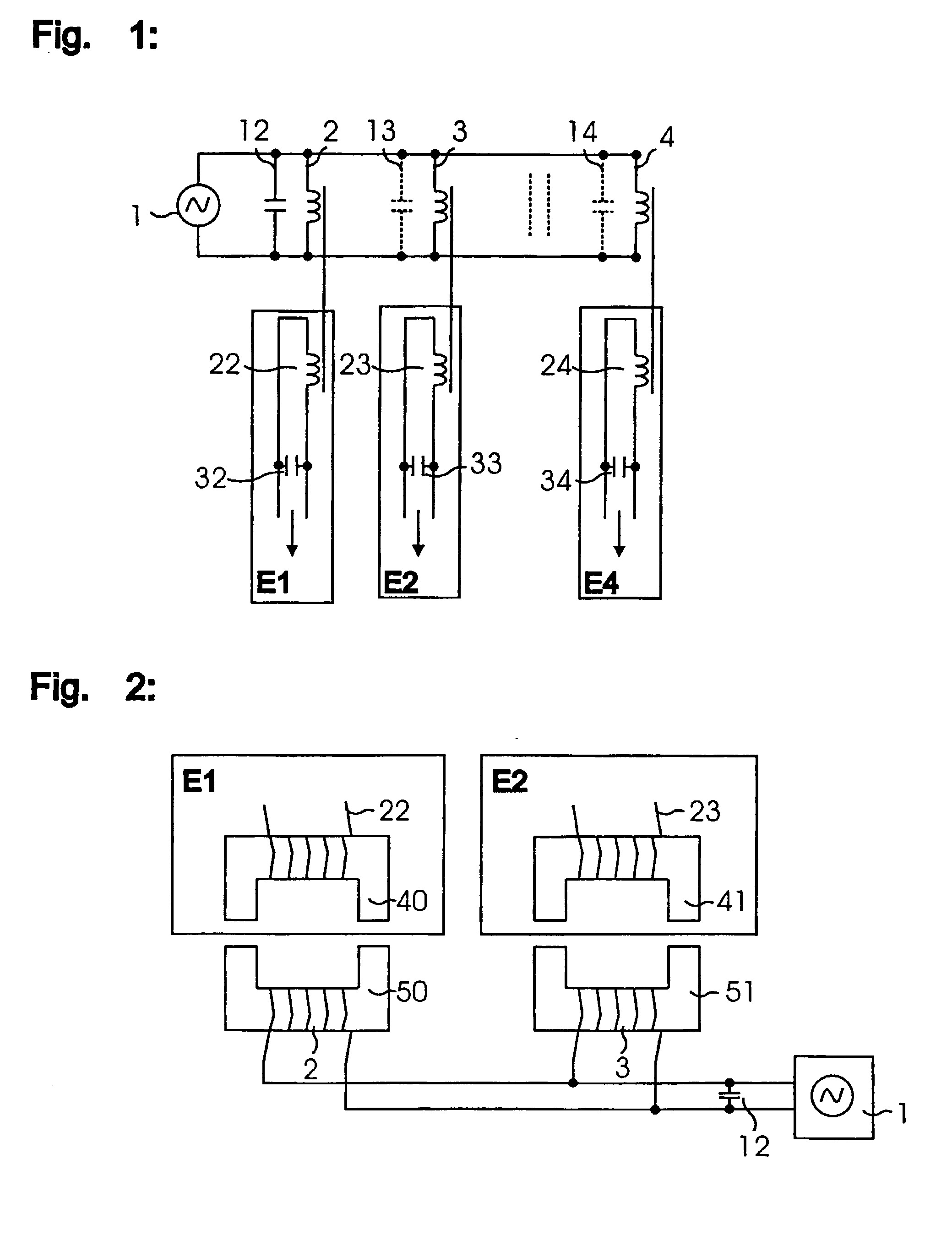
[0033] FIG. 1 illustrates an exemplary inventive arrangement. In the transmitter, an AC voltage source with an integrated control element (1) supplies the inductive coupling elements consisting each of a primary winding (2, 3, 4) and a secondary winding (22, 23, 24). In that array several primary windings are coupled to one respective transmitter whilst the secondary windings are associated with independent receivers in loose mechanical contact with the transmitters. In order to achieve a circuit capable of resonating in parallel, the inductance is supplemented optionally on the primary winding and / or on the secondary winding to form a parallel resonance circuit with appropriate capacitances. The capacitance elements on the primary side (12, 13, 14) are associated with the transmitter whereas the secondary side capacitance elements (32, 33, 34) associated with a respective receiver.

[0034] FIG. 2 is a schematic view of an example of a mechanical structure of an inventive array. It is...


PUM


Abstract

What is described here is an array for the contact-less transmission of electrical signals or energy, respectively, from at least one transmitter to several receivers. The invention is characterised by the provisions that each transmitter comprises an AC voltage or current source, respectively, as well as a plurality of inductive coupling elements supplied from said source, which elements are supplemented by at least one capacitor to form elements capable of resonating, and that furthermore one control element is that controls said AC voltage or current source, respectively, in such a way that the latter operates on a resonant frequency of said elements capable of resonating

Description

[0001] This application is a continuation of pending International Application No. PCT / DE01 / 01497 filed Apr. 18, 2001, which designates the United States and claims priority from pending German Application Nos. 10019371 filed Apr. 18, 2000 and 10026175 filed May 26, 2000.[0002] The present invention relates to an array for the contact-less transmission of electrical signals or energy, respectively.PRIOR ART[0003] Mechanical plug-and-socket connectors are frequently employed for contacting mobile means. Such mechanical contact systems are commercially available in a very wide variety of types and models. As a rule, a comparatively high expenditure is required in order to protect the contact systems from influences from the environment. Here, aspects such as touch-preventing guards, protection from penetrating liquids such as water, oil or even moisture play an important role. Particularly high demands prevail in areas protected from explosion. In order to satisfy such requirements it...

Claims


Application Information

Patent Timeline
IPC IPC(8): G08C17/06H01F38/14H02J5/00H02J17/00H04B5/00
CPCG08C17/06H01F38/14H04B5/0093H02J5/005H04B5/0012H01F2038/146H02J50/402H02J50/005H02J50/12H02J50/05
Inventor LOHR, GEORGWEITHMANN, HERBERTSCHILLING, HARRY
Owner SCHLEIFRING & APPBAU
Why Eureka
Try Eureka