Systems and methods for boundary detection in images

a system and image technology, applied in image enhancement, image data processing, instruments, etc., can solve the problems of inability to detect the edge location, inability to reliably use conventional methods, and inability to accurately detect the edge location

Inactive Publication Date: 2003-05-22
MITUTOYO CORP
View PDF18 Cites 148 Cited by
  • Summary
  • Abstract
  • Description
  • Claims
  • Application Information

AI Technical Summary

Problems solved by technology

However, as is well known in the field of image processing, these conventional methods can become unreliable when the image regions near edges exhibit a high degree of texture or when the edge is defined by a change in texture, color, or other image characteristics that do not always correspond to well-behaved intensity gradients in the image.
The images associated with textured edges are inherently irregular or noisy because each texture region near a particular edge is imaged as a high spatial frequency intensity variation near the edge.
Thus, the intensity gradient-type operations previously discussed tend to return noisy results, which subsequently result in poor detection of the edge locations.
Although filtering operations can be used to reduce the noise in these situations, the filtering operations can also unintentionally further disturb the image in a way that distorts the detected edge location.
Furthermore, in some cases, for example when the average intensities in the texture regions bordering the edge are approximately the same, intensity gradient operations become completely unreliable for finding the location of the edges.
Thus, in such situations, the conventional methods cannot precisely detect an edge location of an image because there is no significant intensity gradient or differential that can be clearly detected.
A common problem associated with these existing image segmentation systems is the rigidity of the system structure.
Systems which include a great variety of texture filters for robustness are too slow to support high-speed industrial throughput requirements.
Systems which limit the number of texture filters and or use a limited number of predetermined parameters usable as thresholds in detecting region membership are often unreliable when applied to a wide variety of textures.
Thus, such existing segmentation systems are insufficiently versatile, robust and / or fast for use in a general-purpose commercial machine vision system.
Furthermore, such segmentation methods have not been well-developed for finding relatively precise positions for edge locations at the boundaries between regions.
However, this method does not disclose any specific methods or tools of particular use for locating the position of a boundary between the classification regions with robustness and precision.
However, the method does not disclose any specific methods or tools for locating the position of a boundary between various sectors with robustness and precision.
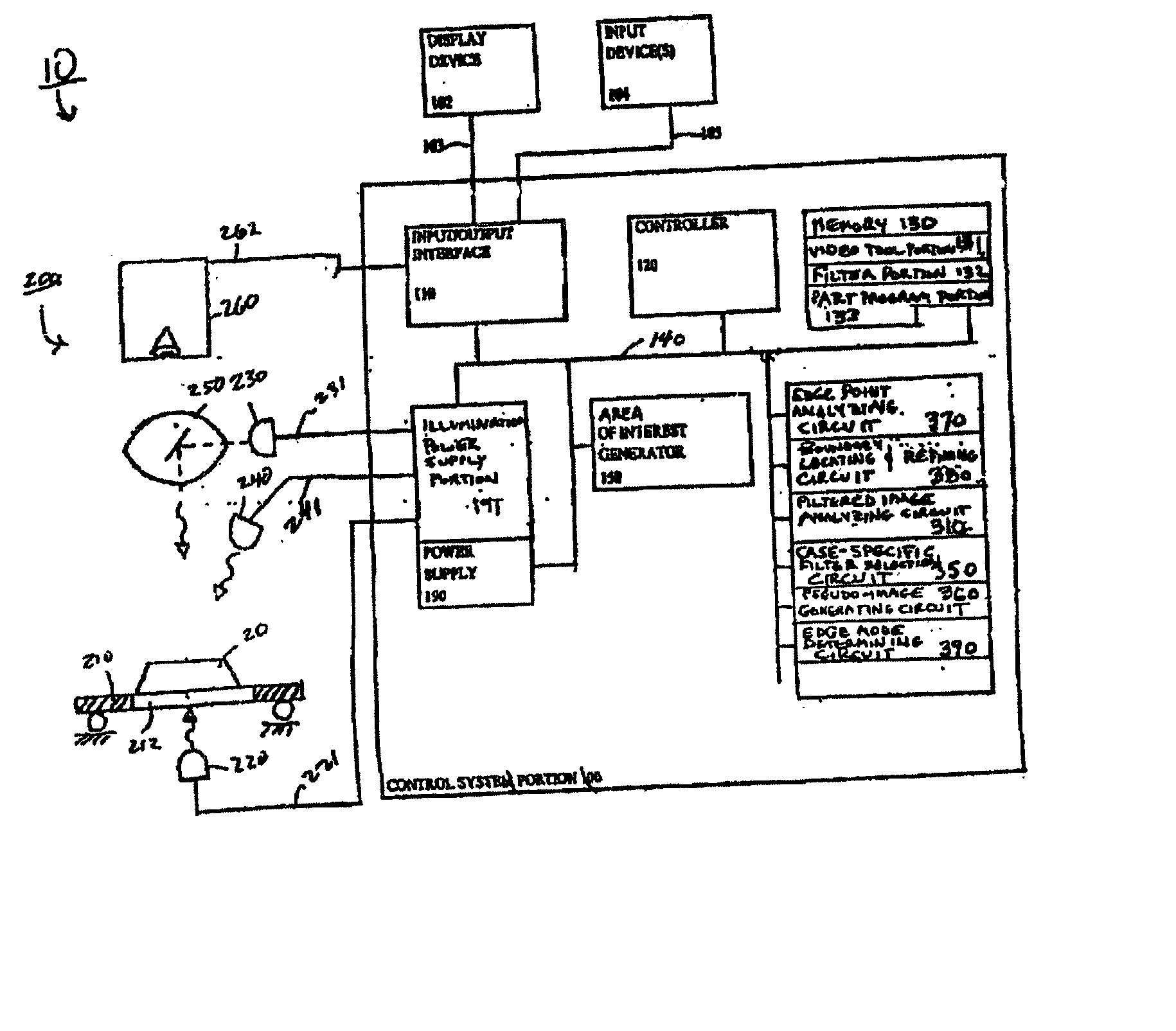
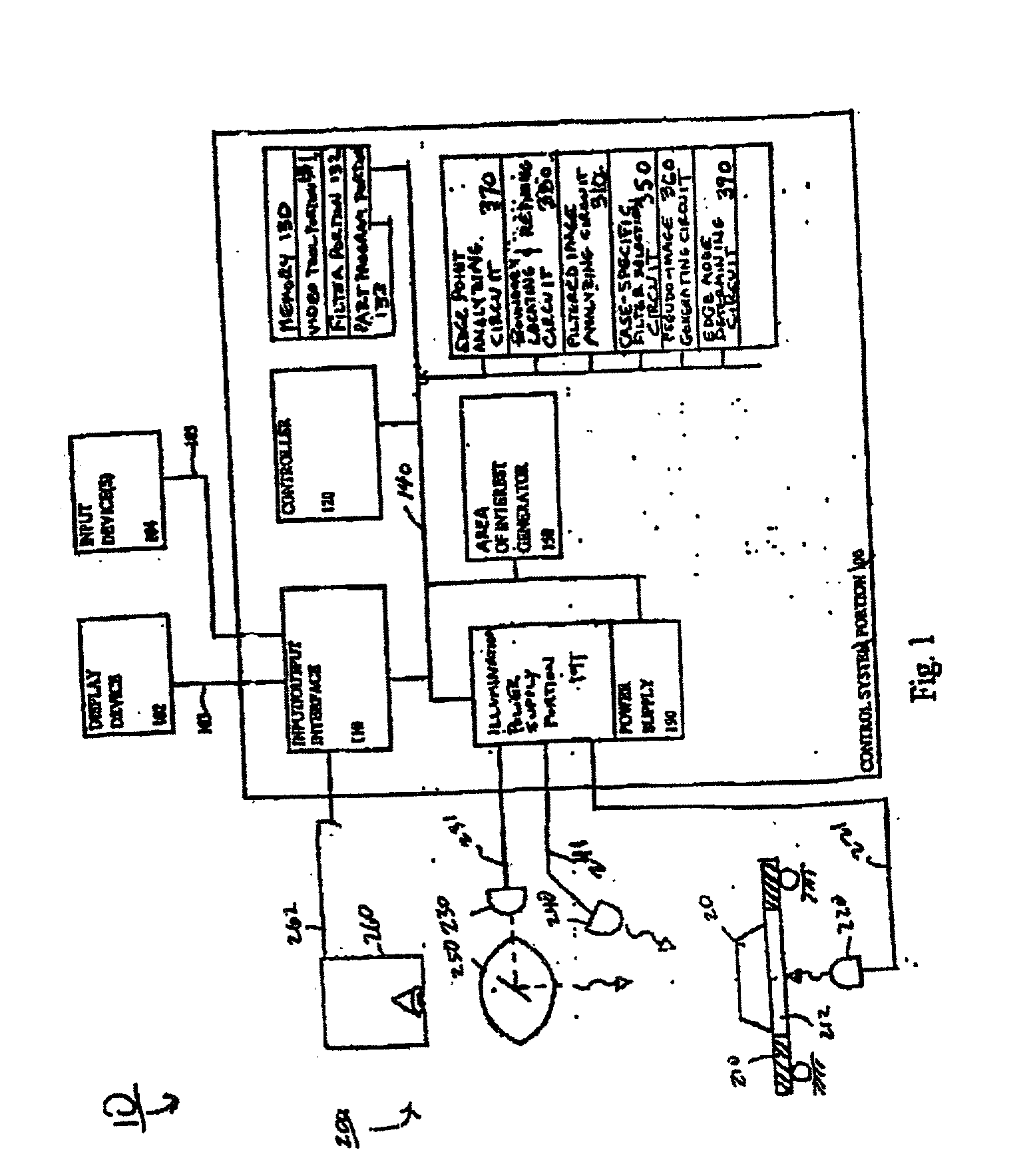
Thus, it is a particular problem to create a machine vision system which locates textured edges in a versatile, robust, fast and relatively precise way, while at the same time adapting and governing that machine vision system edge detection process through the use of a simple user interface that is operable by a relatively unskilled operator.
Accordingly, texture-based segmentation methods and image-specific texture-based segmentation methods have not been well-developed for finding relatively precise positions for edge locations at the boundaries between regions.
Furthermore, such methods have not been combined with a method that automatically streamlines them and subordinates them to other edge or boundary detection operations according to the reasonably well-behaved and predictable characteristics of particular edges found on industrial inspection objects.
Moreover, these methods have not been supported by a simple user interface or compatible "edge tools" which can be used by operators having little or no understanding of the underlying mathematical or image processing operations.
Finally, no conventional machine vision system user interface supports both the operation of conventional intensity gradient-type edge locating operations and texture-type edge-locating operations with substantially similar edge-tools and / or related GUIs, or combines both types of operations for use with a single edge tool.

Method used


Image

  • Systems and methods for boundary detection in images
  • Systems and methods for boundary detection in images
  • Systems and methods for boundary detection in images

Examples


Embodiment Construction

[0043] The systems and methods of this invention can be used in conjunction with the machine vision systems and / or the lighting calibration systems and methods disclosed in U.S. Pat. No. 6,239,554 B1, which is incorporated herein by reference in its entirety.

[0044] With regard to the terms "boundaries" and "edges" as used herein, the terms "boundaries" and "edges" are generally used interchangeably with respect to the scope and operations of the systems and methods of this invention. However, when the context clearly dictates, the term "edge" may further imply the edge at a discontinuity between different surface planes on an object and / or the image of that object. Similarly, the term "boundary" may further imply the boundary at a discontinuity between two textures, two colors, or two other relatively homogeneous surface properties, on a relatively planar surface of an object, and / or the image of that object.

[0045] For simplicity and clarification, the operating principles and desig...


PUM


Abstract

Systems and methods that accurately detect and locate an edge or boundary position based on a number of different characteristics of the image, such as texture, intensity, color, etc. A user can invoke a boundary detection tool to perform, for example, a texture-based edge-finding operation, possibly along with a conventional intensity gradient edge-locating operation. The boundary detection tool defines a primary region of interest that will include an edge or boundary to be located within a captured image of an object. The boundary detection tool is useable to locate edges in a current object, and to quickly and robustly locate corresponding edges of similar objects in the future.

Description

[0001] 1. Field of Invention[0002] This invention relates to boundary detection and boundary location determination between two regions in images.[0003] 2. Description of Related Art[0004] Many conventional machine visions systems used in locating the edges of features in images are based primarily or exclusively on applying gradient operations to the intensity values of the original image pixels. In applying gradient operations, these systems perform edge-location using the contrast inherent in the original intensity of an image. This operation is often used for machine visions systems that emphasize determining the location of edges in images of man-made work pieces with a high degree of precision and reliability. In these cases, the geometry of the edges is often well-behaved and predictable, thus providing constraints that can be applied to the edge location operations so that good results may be obtained for the majority of these images. It is also well known to use filters pri...

Claims


Application Information

Patent Timeline
Patent Type & Authority Applications(United States)
IPC IPC(8): G06T1/00G01B11/02G06T5/00G06T5/20G06T7/60
CPCG06T2207/10016G06T7/0083G06T7/12
Inventor TESSADRO, ANA M.
Owner MITUTOYO CORP
Why Eureka
Try Eureka