
Fluid flow meter for gravity fed intravenous fluid delivery systems

a flow meter and fluid delivery technology, applied in the direction of flow monitors, liquid/fluent solid measurements, medical devices, etc., can solve the problems of non-gravity fed devices, inconvenient metering, and inability to accurately control the flow, etc., to achieve accurate metering and regulation

Inactive Publication Date: 2003-06-12
MEDRIP
View PDF4 Cites 14 Cited by
  • Summary
  • Abstract
  • Description
  • Claims
  • Application Information

AI Technical Summary

Benefits of technology

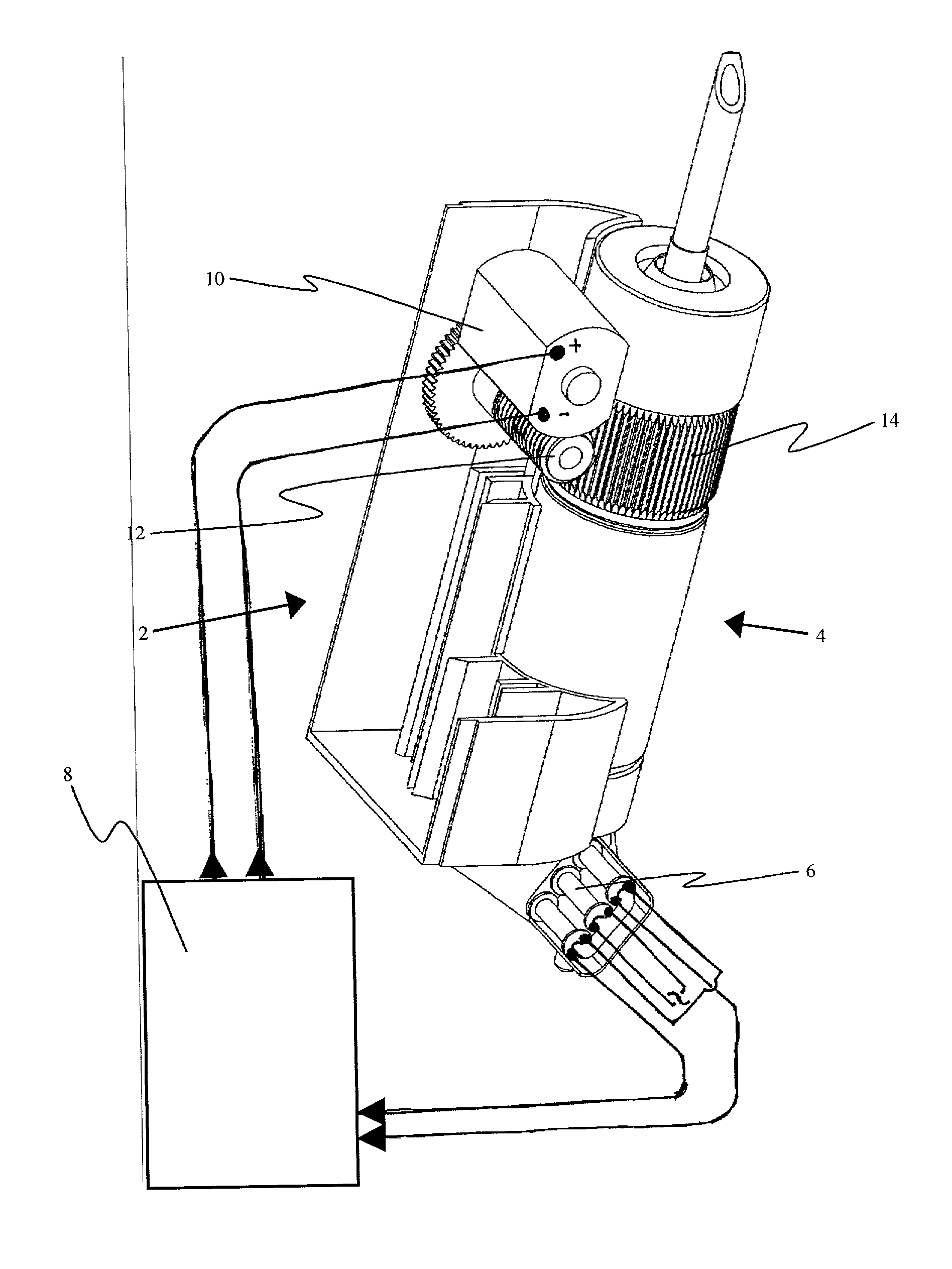
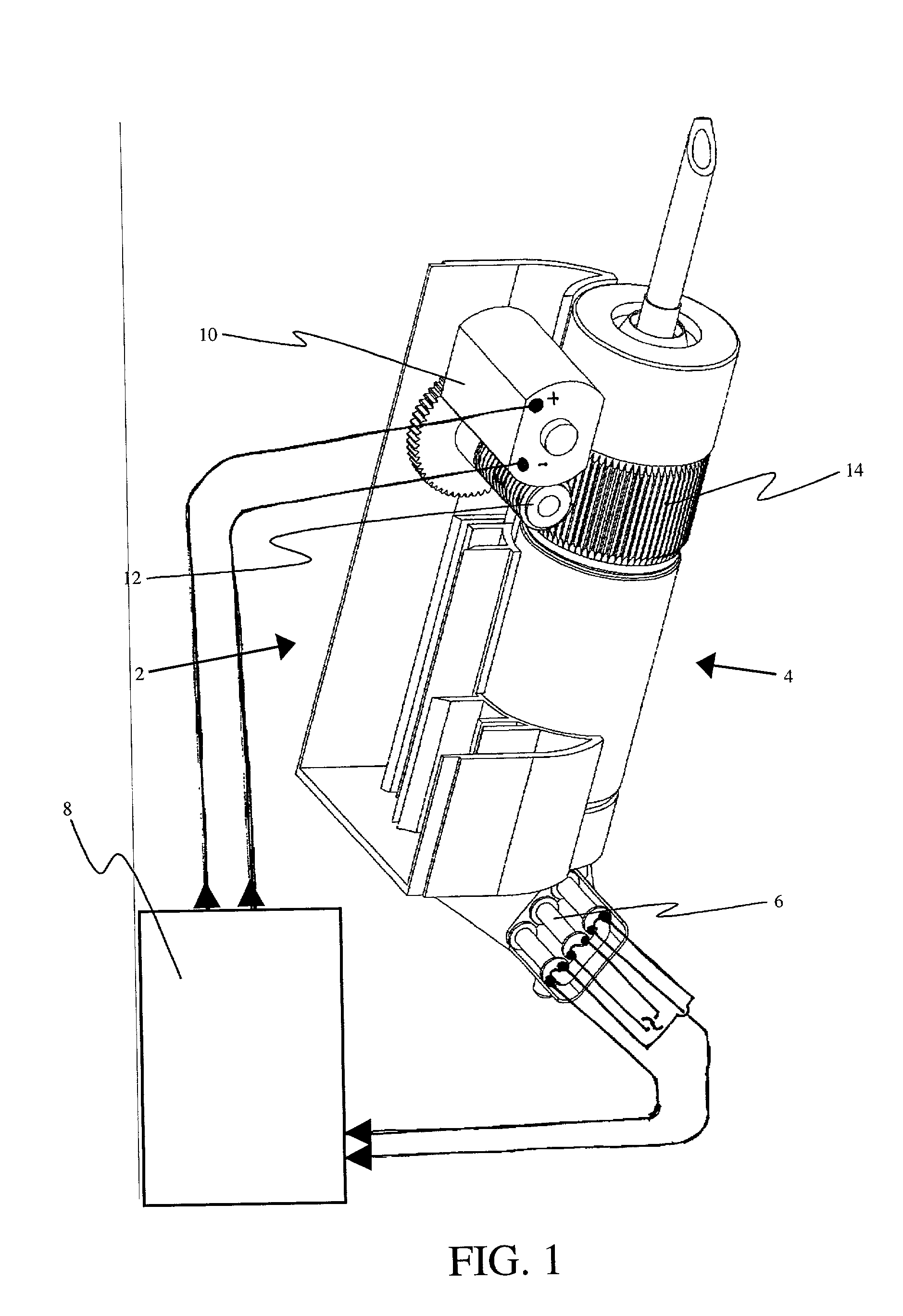
[0007] The present invention is a flow metering system for accurately metering and regulating the flow rate of fluid in a gravity fed intravenous fluid delivery system.
[0020] There is also provided according to the teachings of the present invention, a flow metering system for accurately metering and regulating the flow rate of fluid flowing through a tube of a fluid delivery system, the flow metering system comprising: a) an adjustable flow regulator assembly having a regulator inlet, the flow regulator thereby receiving a flow of fluid, the flow regulator being configured so as to regulate the flow of fluid through the regulator, the regulator including an adjustment mechanism responsive to an adjustment actuator, the flow regulator further having a regulator outlet; and b) the flow meter of claim 1 in fluid communication with the regulator; wherein the adjustment actuator is in electronic communication with, and responsive to, the processing unit, so as to regulate the flow.
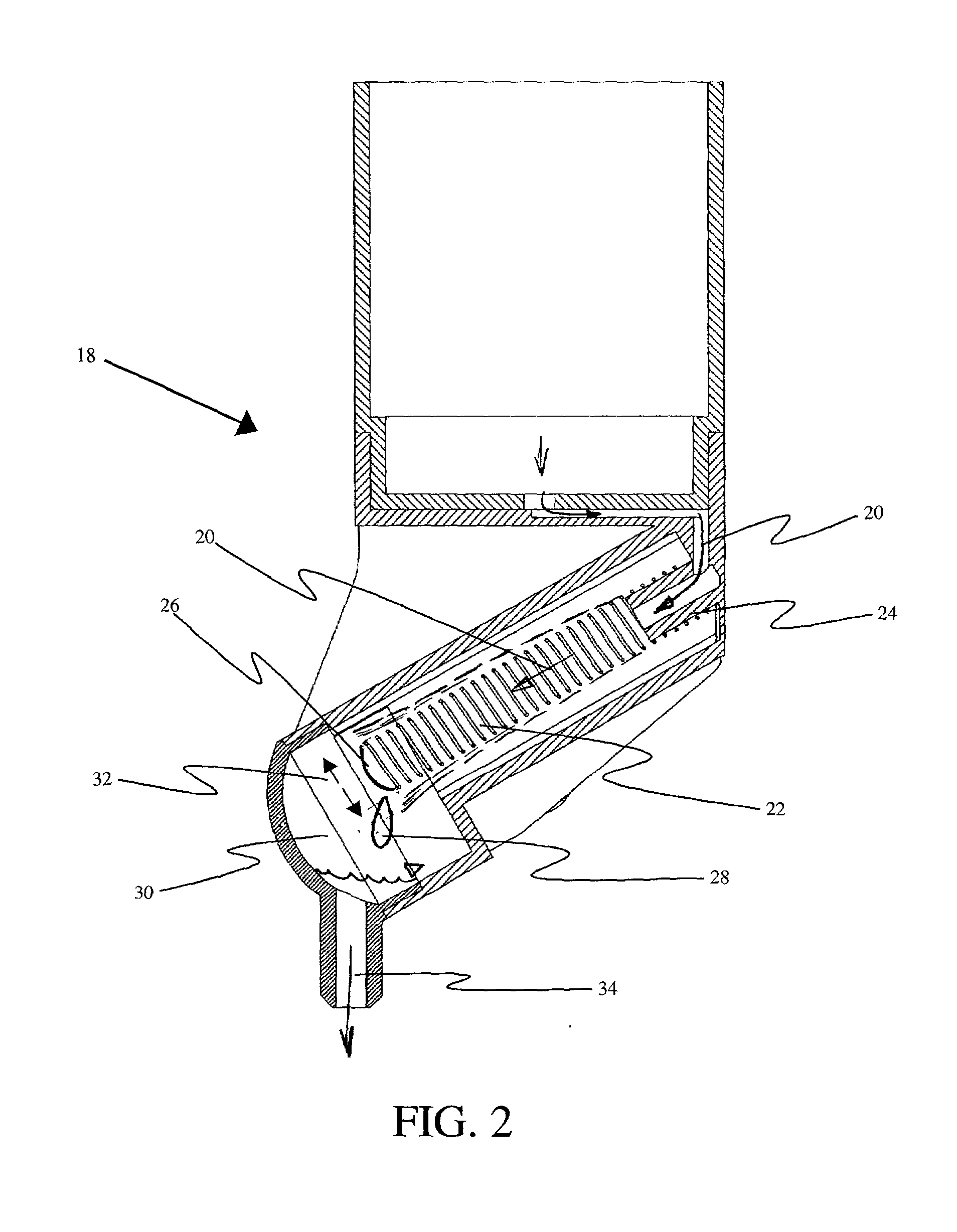
[0026] There is also provided according to the teachings of the present invention, a flow metering method for accurately metering the flow rate of fluid flowing through a tube of a fluid delivery system, the flow metering method comprising: a) directing the flow along a fluid flow path guide, the flow path guide being deployed at an angle with an upper end fixedly attached to a meter inlet and a lower end suspended above a reservoir attached to a meter outlet, the flow path guide having an initial position, the flow path guide configured so as to have a given elastic resiliency such that when bent and subsequently released the flow path guide returns to the initial position, the bending being caused by weight from a build up of fluid at a lower end and the return of the flow path guide to the initial position occurring when a drop is released from the lower end of the flow path guide; b) sensing movements of the flow path guide; and c) processing output resulting from the sensing, so as to derive fluid flow rate.

Problems solved by technology

A typical gravity fed intravenous system may be as simple as an IV bag hanging on a pole and a medical staff person manually adjusting a valve to limit the flow rate, but not control it accurately.
Even the nominal orifice diameter is not uniform throughout the industry.
There a several problems associated with these non-gravity fed devices.
They provide fluid medication to the patient at high pressure this may result in physical damage to the vein or artery of the patient.
With pressurization comes the chance of bubbles in the system, and these devices must include bubble detectors.
Their complexity of design results in complex operation that may increase the opportunity for malfunction and the need for enough energy to power the device.
The need for energy usually requires that the device be plugged into a wall outlet, there by restricting the mobility of the patient while receiving treatment Further, the intricacy of manufacture results in high purchase costs to the consumer, i.e. hospitals and clinics, which generally have tight and limited budgets.
Therefore, these devices are available in relatively limited quantities and used on a "most needed case" basis.
These are still active pumps and suffer from all of problems enumerated above.
While this provides a means of substantially constant monitoring not available from human staff, the problems of drop size and fluid viscosity still exist since this is still just counting the drops.

Method used


Image

  • Fluid flow meter for gravity fed intravenous fluid delivery systems
  • Fluid flow meter for gravity fed intravenous fluid delivery systems
  • Fluid flow meter for gravity fed intravenous fluid delivery systems

Examples


Embodiment Construction

[0040] The present invention is a flow metering system for accurately metering and regulating the flow rate of fluid in a gravity fed intravenous fluid delivery system.

[0041] The principles and operation of a flow metering system according to the present invention may be better understood with reference to the drawings and the accompanying description.

[0042] Before turning to details of the present invention, it should be appreciated that the present invention provides a flow meter that is preferably configured for use in conjunction with the flow regulator of U.S. Pat. No. 6,254,576 (as in the preferred embodiment discussed here). However, the flow meter may be configured to be individually combined with other corresponding components, or for use as a stand-alone device. The flow meter will be discussed in FIGS. 2-4. The flow regulator, and control thereof, will be discussed in FIGS. 5 and 6. It should be note here that while in the following discussion the flow meter is deployed d...


PUM


Abstract

The present invention is a flow metering system for accurately metering and regulating the flow rate of fluid in a gravity fed intravenous fluid delivery system. The fluid flow is directed through a flow path guide that is suspended at an angle from one end. As the fluid flows through the flow path guide, the flow path guide bends due to the weight of the fluid. A drop of fluid forms at the end of the flow path guide then falls off, thereby releasing the flow path guide, which springs back it its original position. The sequence of drops and springing back continues throughout the fluid delivery procedure, and is monitored by sensors. The resultant data is used by a processor to determine the flow rate of the fluid. The flow rate may be adjusted as needed by a flow regulator that is responsive to an adjustment actuator that is controlled by the processor.

Description

FIELD AND BACKGROUND OF THE INVENTION[0001] The present invention relates to gravity fed intravenous delivery systems and, in particular, it concerns a system for metering and regulating the fluid flow thereof.[0002] A typical gravity fed intravenous system may be as simple as an IV bag hanging on a pole and a medical staff person manually adjusting a valve to limit the flow rate, but not control it accurately. Traditionally, the flow rate of the fluid from the IV bag was roughly measured with a drip chamber at the IV bag and controlled by a clamp varying the restriction in a delivery line extending between the drip chamber and the patient. A medical staff person visually counts the drop rate in the drip chamber and manually sets the clamping or pinching device to achieve a desired flow rate. The accuracy of this system assumes the consistency in volume of each drop of fluid into the drip chamber. However, the drop size is dependent on the orifice diameter, the inner and the outer d...

Claims


Application Information

Patent Timeline
Patent Type & Authority Applications(United States)
IPC IPC(8): A61M5/168G01F3/00
CPCA61M5/16877A61M2205/3379G01F3/00
Inventor SHEKALIM, AVRAHAM
Owner MEDRIP
Learn More