Light-scattering film and liquid crystal device using the film

a liquid crystal device and light-scattering film technology, applied in the direction of instruments, polarising elements, optical elements, etc., can solve the problems of inability to enhance a light intensity (brightness) in a viewing direction of a viewer, no light-scattering film has such a property, and production costs are very expensive. , to achieve the effect of sufficient brightness, high directivity and lightening the display screen

Inactive Publication Date: 2003-06-26
DAICEL CHEM IND LTD +1
View PDF4 Cites 50 Cited by
  • Summary
  • Abstract
  • Description
  • Claims
  • Application Information

AI Technical Summary

Benefits of technology

0071] In such a reflective LCD apparatus, an incident light from the viewer side is transmitted and diffused through the light-scattering film and reflected by the reflecting means, and the reflected light is transmitted and rescattered through the light-scattering film. Therefore, even in the reflective LCD apparatus having the light-scattering film, the display screen can be lightened due to high directivity, the sufficient brightness can be ensured even in color display, and the sharp color image can be realized in the color display-mode reflective LCD apparatus.

Problems solved by technology

That is, a conventional light-scattering film has a property that a bottom of a light intensity (brightness) is spread out in a distribution of a scattered-light intensity, as a result, it is impossible to enhance a light intensity (brightness) on a viewing direction of a viewer.
However, there is no having such a property in a conventional light-scattering film in principle.
However, since these production processes are complex, the production cost is very expensive and therefore it is difficult to produce in large quantities substantially.
However, the production process of this light-scattering sheet is complex and it is necessary to use a special photographic sensitive material utilizing hologram.

Method used


Image

  • Light-scattering film and liquid crystal device using the film
  • Light-scattering film and liquid crystal device using the film
  • Light-scattering film and liquid crystal device using the film

Examples


example 1

[0078] A commercially available acrylic liquid crystal compound (polymerizable acrylic liquid crystal) (100 parts by weight) and cyano-series liquid crystal compound (100 parts by weight) were mixed to prepare a liquid crystal mixture. The liquid crystal mixture showed a liquid crystal state at room temperature. The refraction index of the mixture was measured by means of an Abbe refraction index detector, and the birefringence index was 0.18 (ne=1.70, no=1.52). On the other hand, 200 parts by weight of SAN resin (a styrene-acrylonitrile copolymer, manufactured by Technopolymer Co, Ltd., 290ZF, refraction index=1.56) was dissolved in 800 parts by weight of cyclohexane, and to thus obtained solution was mixed the liquid mixture and 2 parts by weight of a polymerization initiator (a light-polymerization initiator). After mixing, thus obtained solution showed transparent isotropic phase. The solution was coated on a transparent conductive layer (ITO)-attached glass plate, and dried at ...

example 2

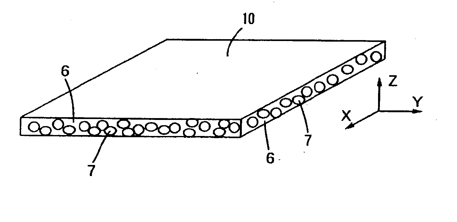
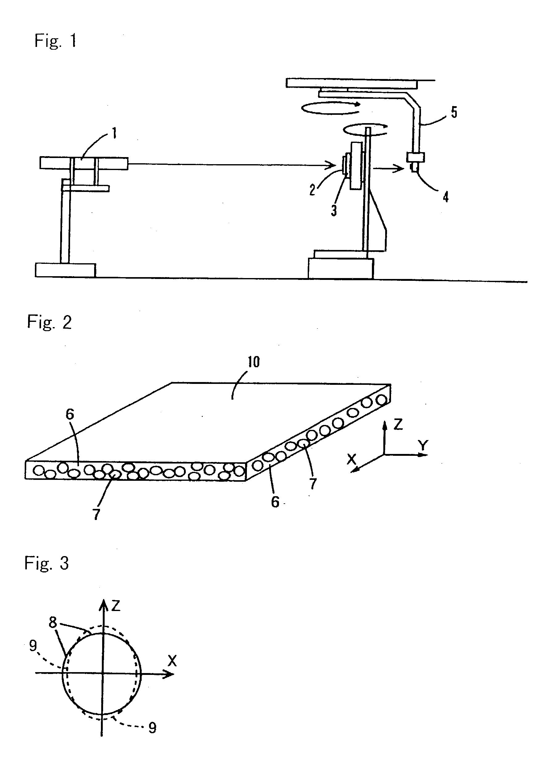
[0083] A light-scattering film 80 .mu.m thick was produced as the same manner as in Example 1. Incidentally, the sample stand 3 was rotated so that an oblique incident angle was 30.degree. on the film surface by using the apparatus shown in FIG. 1, then an irradiation of a polarized light was conducted and received, and a rectilinear transmittance at 30.degree. of an oblique incident light of the light-scattering film was measured as 10%.

[0084] Furthermore, each of the light-scattering films obtained from Example 2 and Comparative Example 1 was attached to the sample stand 3 by rotating the sample stand 3 at an oblique incident angle of 30.degree., then irradiating a linear polarized light, and receiving the light with rotating the arm 5, a scattering property relative to a scattering angle at an incident light of 30.degree. was determined. The results are shown in FIG. 9. Incidentally, in the Example, a scattering angle corresponding to a linearly transmitted direction is 30.degree...


PUM

PropertyMeasurementUnit
incident angleaaaaaaaaaa
transmittanceaaaaaaaaaa

Abstract

A light-scattering film 10 is obtained by subjecting a birefringent material in a resin layer to orientation treatment, in which at least one component selected from a transparent resin 6 and a scattering material 7 is the birefringent material (e.g., a birefringent resin, a liquid crystalline material). According to the light-scattering film, in the case where a linear polarized light in which a vibrating direction and a propagating direction exist in a plane containing a surface-directional axis of the film and a thickness-directional axis of the film is incident at a film surface, the rectilinear transmittance of the incident light shows maximum at an oblique incident direction to the film surface (e.g., incident angle of 20 to 89°). The rectilinear transmittance of the incident light from a direction perpendicular to the film surface is 0 to 30%, and the rectilinear transmittance of the incident light from an oblique direction having an incident angle of 40 to 70° to the film surface is 50 to 100%. Directivity in a light-scattering property of the light-scattering film is improved, and even when an incident light comes from an oblique direction, brightness of the display surface from a front direction is improved. Therefore, the film is useful for employing in combination with a polarized plate of the liquid crystal display apparatus.

Description

[0001] The present invention relates to a light-scattering film utilized for a variety of optical apparatus, and a liquid crystal display apparatus using the film.[0002] In a variety of optical apparatus such as a backlight unit for a transmittable liquid crystal display apparatus, and a reflective liquid crystal display apparatus, a light-scattering film has been utilized for an effective use of a light source. The light-scattering film has need of not only brightness of a display surface but also light-scattering properties excellent in brightness uniformity to accept requests as high luminance and low electric power consumption.[0003] A conventional light-scattering film has a structure in which resin beads varying each other in refraction index are dispersed in a transparent matrix resin, and a light-scattering property of the film accords to Gaussian distribution in principle. Therefore, a scattered light is consequently scattered in direction other than a viewing direction, an...

Claims


Application Information

Patent Timeline
Patent Type & Authority Applications(United States)
IPC IPC(8): B32B7/02C08J5/18C08L101/00G02B5/02G02B5/30G02F1/1335G02F1/13357G02F1/13363
CPCG02B5/0242G02B5/0268G02F1/133504G02B5/3008G02B5/0278G02F1/1335
Inventor UCHIDA, TATSUOTAKEMOTO, HIROYUKI
Owner DAICEL CHEM IND LTD
Why Eureka
Try Eureka