Main bearing cap for internal combustion engines

Inactive Publication Date: 2003-06-26
FORD GLOBAL TECH LLC
View PDF10 Cites 3 Cited by
  • Summary
  • Abstract
  • Description
  • Claims
  • Application Information

AI Technical Summary

Benefits of technology

[0005] The purpose of the present invention is to achieve a main bearing cap of the type described by way of introduction, which improves the strength of the central portion of the iron alloy core and reduces bearing distortion without reducing the mechanical grip between the core and the aluminum material.
[0007] By dividing the single centrally located channel of the previously known core described above into two channels displaced from the center section of the central portion of the core, the advantage is improved strength of the most loaded section. An additional advantage is reduced bearing distortion caused by thermal expansion of the aluminum due to displacing the channels from the most loaded section.
[0008] Yet another advantage is the reduction of the mass of the core compared with the previously known core described above while maintaining the strength. This is achieved by the two channels displaced from the center section of the central portion which allow the central section to be designed essentially U-shaped with a thickness decreasing from the center towards the side portions.

Problems solved by technology

The lowest possible weight can, however, only be achieved at the cost of increased mechanical engine noise due to the greater thermal expansion of the aluminum material causing in increased bearing clearance.
This channel weakens the core in its most loaded section, while the aluminum alloy in it, due to the higher thermal expansion of the aluminum alloy compared with the iron alloy, causes higher bearing distortion in the most loaded section.

Method used


Image

  • Main bearing cap for internal combustion engines
  • Main bearing cap for internal combustion engines

Examples


Embodiment Construction

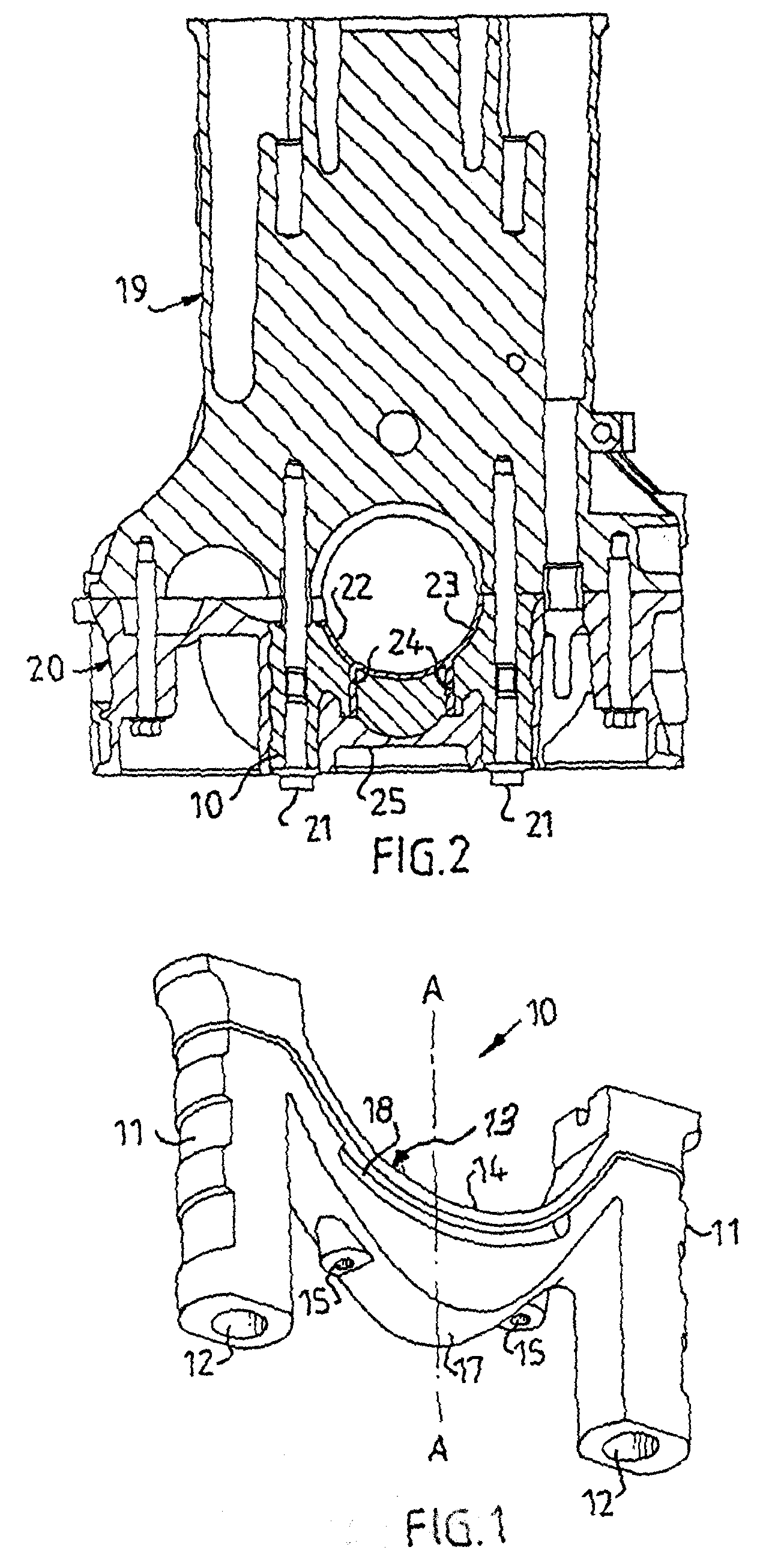
[0012] Figure 1 shows an iron alloy core 10, according to the present invention. It has tubular lateral portions 11 with bores 12 for bolts. An essentially U-shaped central portion 13 between the lateral portions 11 has a semi-circular upper limiting surface 14. As can be seen, the central portion 13 has a maximum thickness in its center section A-A, the thickness decreasing gradually towards the lateral portions 11. Two through-channels 15, equally spaced from the center section A-A, extend from the upper surface 16 of the core 10 to the under side 17 of the core. Two pockets 18 are formed in opposite sides of the central portion 11 of the core 10 to increase the mechanical grip between the in-cast core and the surrounding aluminum alloy.

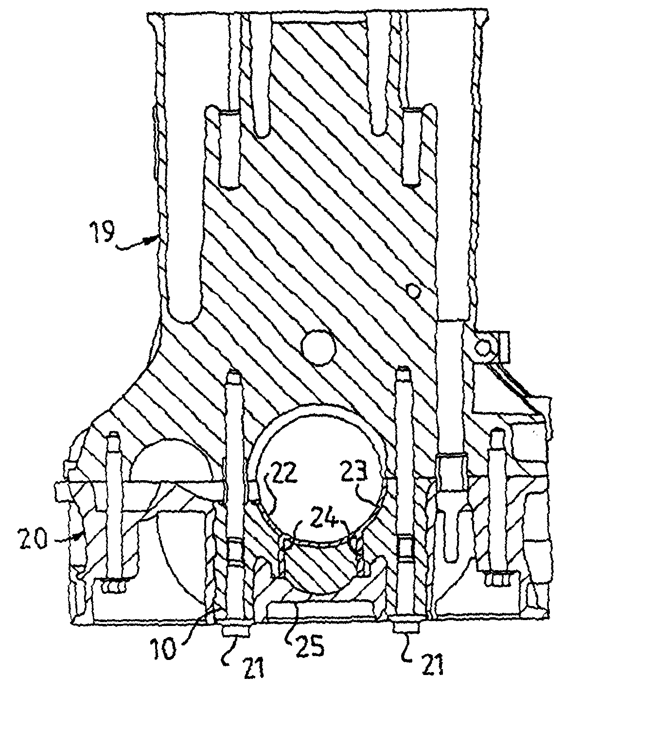
[0013] Figure 2 shows an engine block 19 made of an aluminum alloy. A main bearing bridge 20 made of an aluminum alloy with in-cast iron alloy cores 10 is attached to the engine block by means of bolts 21 in the bores 12 in the lateral portions 3 o...


PUM

PropertyMeasurementUnit
Thicknessaaaaaaaaaa
Mechanical propertiesaaaaaaaaaa
Surfaceaaaaaaaaaa

Abstract

Abstract of Disclosure A main bearing cap (20) for an internal combustion engine consists of an aluminum alloy with an iron alloy core (10). The cap has a supporting surface (22) for a bearing shell. The iron alloy core has a central portion (13) with two spaced apart through-channels (15) filled with an aluminum alloy (24) forming a coherent mass with an aluminum layer (23) the outer limiting surface of which forms the supporting surface (22).

Description

Background of Invention[0001] Field of the Invention[0002] The present invention relates to a bearing cap for a main bearing in an internal combustion engine. The cap consisting partially of an aluminum alloy and partially of an iron alloy forming a core in the aluminum material. The core has lateral portions with bores for mounting bolts and a central portion between the lateral portions. The central portion terminates at a distance from a supporting surface for a bearing shell, the supporting surface being the outer limiting surface of an aluminum alloy layer outside the iron core.[0003] Background Information[0004] It is known in the art to use main bearing caps made entirely of aluminum in aluminum engine blocks to provide a design which is as light as possible. The lowest possible weight can, however, only be achieved at the cost of increased mechanical engine noise due to the greater thermal expansion of the aluminum material causing in increased bearing clearance. It is also ...

Claims


Application Information

Patent Timeline
IPC IPC(8): F02F7/00F16C9/02F16M1/025
CPCF16C9/02F16M1/025F02F7/0053Y10T29/49705F05C2201/0439F05C2251/042F05C2201/021
Inventor RENGMYR , STAFFAN
Owner FORD GLOBAL TECH LLC
Why Eureka
Try Eureka