
User interface for a network-based mask defect printability analysis system

a network-based mask and printability technology, applied in the field of integrated circuit manufacturing, can solve the problems of extremely complicated mask simulation tools to learn and use effectively, and achieve the effect of increasing efficiency

Inactive Publication Date: 2003-07-03
SYNOPSYS INC
View PDF59 Cites 76 Cited by
  • Summary
  • Abstract
  • Description
  • Claims
  • Application Information

AI Technical Summary

Benefits of technology

[0020] Mask simulation tools are typically extremely complicated to learn and to use effectively. Moreover, the mask maker and mask user can be located in different buildings, cities, or countries. Therefore, providing access to a mask simulation tool over a wide area network (WAN) to multiple on-line users can be very cost effective and productive. Specifically, clients can now advantageously leverage a core of highly trained engineers who work for the simulation server provider. Moreover, because clients need only access, not run, the simulation server, the clients can use standard personal computers instead of expensive workstations. Furthermore, in a network-based simulation server, multiple users can view the same mask image, as well as its simulation and analysis results, and provide real-time comments to each other as simulation and analysis are performed, thereby encouraging invaluable problem-solving dialogue among users.
[0024] The user interface can also provide a simulation icon for initiating a simulation. The simulation icon can include means for identifying an image to be simulated, means for allowing simulated images to be moved in three-dimensional directions, and means for generating a one-dimensional plot from the image. The one-dimensional plot can include a graph plotting aerial image intensity versus position and / or a graph plotting process latitudes. In one embodiment, the image includes both a defect image and a layout image corresponding to the defect image. In this case, the simulation icon can further include means for comparing the simulated defect image and the simulated layout image. To increase efficiency when multiple mask images are being simulated, the simulation icon can further include means for creating a simulation template or a test template.4.

Problems solved by technology

Mask simulation tools are typically extremely complicated to learn and to use effectively.

Method used


Image

  • User interface for a network-based mask defect printability analysis system
  • User interface for a network-based mask defect printability analysis system
  • User interface for a network-based mask defect printability analysis system

Examples


Embodiment Construction

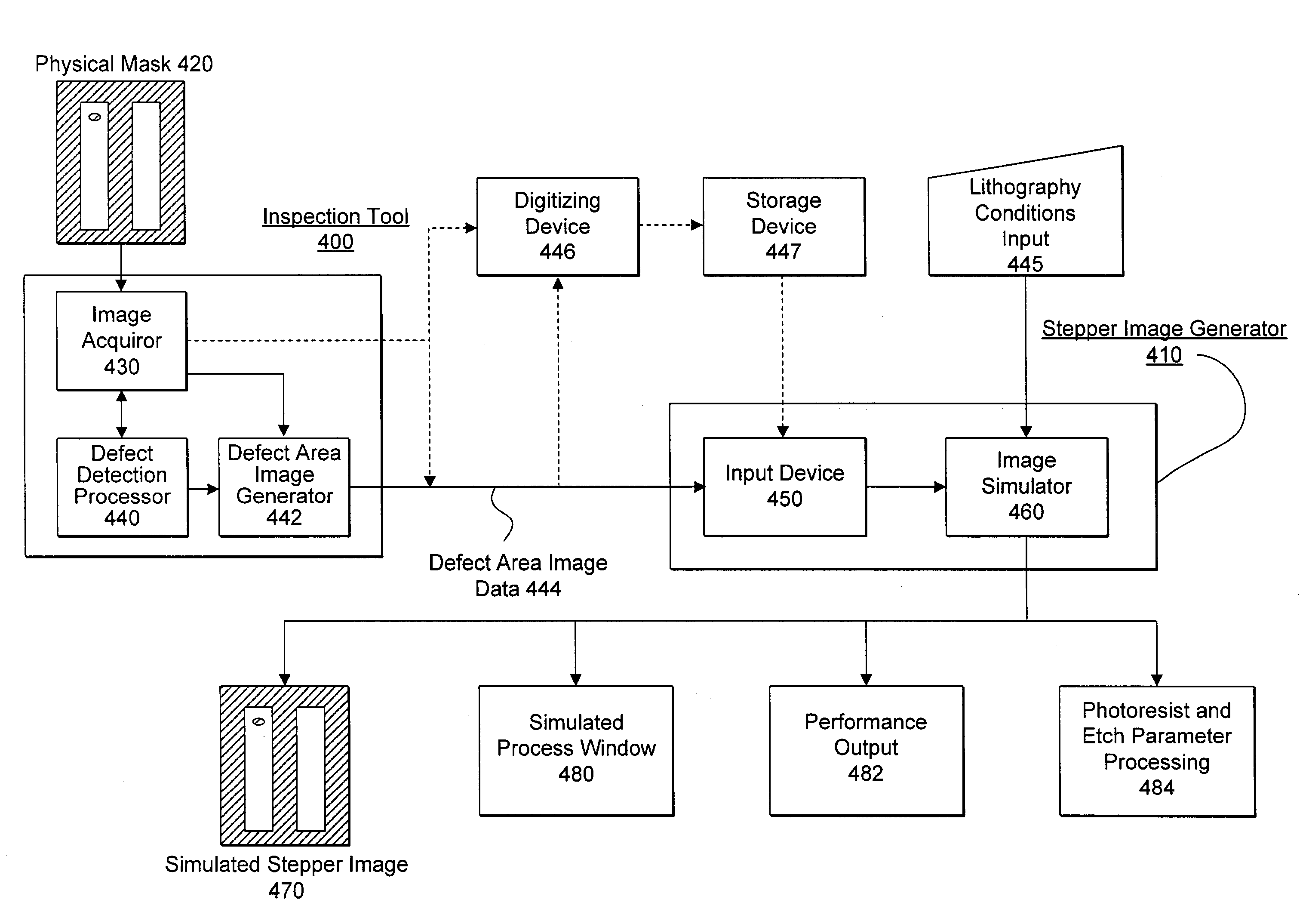
[0053] Photolithography is a process whose input is a mask and whose output is the printed patterns on a wafer. The printed result from a mask is what design engineers, lithographers, and mask manufacturers really care about. Using prior methods, the only way to inspect this printed result was to perform an actual wafer exposure and therefore incur potentially unnecessary costs in time and money. The present invention solves some of the problems of these prior methods by providing for mask inspection that takes printability into account without the need for the expensive steps of actually exposing a wafer. The present invention is capable of using a captured image of a mask--that accurately enough represents the physical mask (i.e. such as from a high resolution optical microscope or a scanning electron microscope)--and using that captured image to simulate the wafer exposure that the mask would provide under a given set of stepper conditions. Thus, when an initial mask inspection f...


PUM

PropertyMeasurementUnit
wide area networkaaaaaaaaaa
real-time communicationaaaaaaaaaa
defectaaaaaaaaaa

Abstract

Mask simulation tools are typically extremely complicated to learn and to use effectively. Therefore, providing access to a mask simulation tool over a wide area network (WAN) to multiple on-line users can be very cost effective. Specifically, in a network-based simulation server, multiple users can view the same mask image, simulations, and analysis results and provide real-time comments to each other as simulation and analysis are performed, thereby encouraging invaluable problem-solving dialogue among users. The user interface for this mask simulation tool can advantageously facilitate this dialogue. For example, the user interface can include an enter box for a user to enter a message and a talk box for capturing any message sent by any user of the simulation tool using the enter box.

Description

1. RELATED APPLICATIONS[0001] This application is a divisional of U.S. patent application Ser. No. 09 / 544,798 entitled, "Method And Apparatus For A Network-Based Mask Defect Printability Analysis System", filed on Apr. 7, 2000, which is a continuation-in-part of U.S. patent application Ser. No. 09 / 130,996 entitled "Visual Inspection And Verification System", filed on Aug. 7, 1998 which in turn relates to U.S. Patent Application Serial No. 60 / 059,306, entitled "Mask Verification Correction and Design Rule Checking", filed on Sep. 17, 1997, incorporated by reference herein.2. THE BACKGROUND OF THE INVENTION[0002] a. The Field of the Invention[0003] This invention relates to the field of integrated circuit manufacturing. In particular, the invention relates to a user interface in a system for inspection of defects on masks used in the manufacture of integrated circuits.[0004] b. Description of Related Art[0005] In designing an integrated circuit (IC), engineers typically rely upon comp...

Claims


Application Information

Patent Timeline
Patent Type & Authority Applications(United States)
IPC IPC(8): G01Q30/02G01Q30/04G01Q60/18G01Q60/24G01Q80/00G01Q90/00G03F1/26G03F1/36G03F1/84G03F7/14G03F7/20G06F17/50G06T7/00H01L21/027
CPCG03F1/26G03F1/36G03F1/84G03F7/70441G03F7/705Y10S977/839G06T7/0004G06T2207/30148Y10S977/887Y10S977/953G06F17/5068G06F30/39
Inventor PANG, LINYONGHOWARD, DANIEL WILLIAMKARKLIN, LINARD
Owner SYNOPSYS INC
Learn More