
Inflatable insulating liners including phase change material

a technology of phase change material and insulating liners, which is applied in the direction of cooling fluid circulation, domestic cooling apparatus, lighting and heating apparatus, etc., can solve the problems of time-sensitive, perishable foodstuffs, and relatively slow surface transportation, so as to reduce the number of welding passes required, improve manufacturing efficiency, and reduce spoilage

Inactive Publication Date: 2003-07-10
CARGO TECH
View PDF38 Cites 52 Cited by
  • Summary
  • Abstract
  • Description
  • Claims
  • Application Information

AI Technical Summary

Benefits of technology

[0023] The inflatable walls significantly reduce conductive heat losses through the insulating bag. An enhanced insulative performance can be obtained by replacing environmental air as the inflating gas with an inert, low conductivity gas, such as argon.
[0024] Further insulating enhancement can be obtained by minimizing losses caused by radiant heat transfer. One method of achieving lower radiant thermal losses utilizes a metalized reflective layer formed on one of the surfaces of the plastic film. When configured in a manner resulting in the placement of the reflective layer on the inner surface of the outer wall (which is normally the "hot face"), a low emissivity surface is obtained. A similar metalized surface provided on the opposing, inner surface of the interior wall film, normally the "cold face,"acts as a radiant barrier.
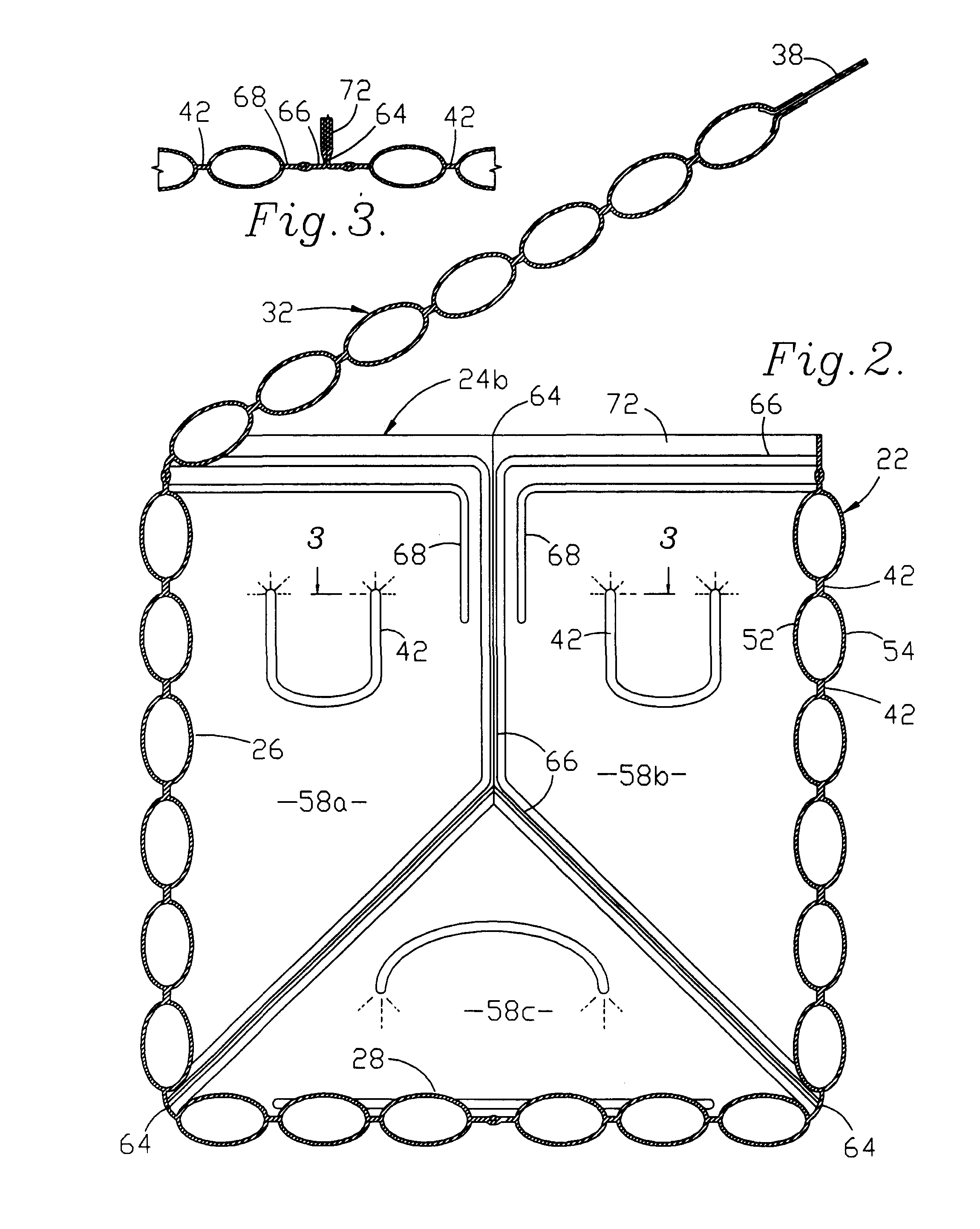
[0025] An alternate strategy for minimizing radiant thermal losses (as well as convective heat losses), makes use of baffles placed within the inflated wall panels. One type of baffle relies upon a stiffened material, and will, if carefully dimensioned, self-center between contracting adjacent attachment seams during inflation of the wall structure. Emplacement of the stiffened baffles within the wall structure during the fabrication thereof may be obtained by providing a sheet of baffle material having slots formed therein that dimensionally conform in both size and location to the rf welding seams. The slotted baffle material is then received between the pair of plastic film layers prior to rf welding.
[0026] An alternative baffle material makes use of a continuous sheet of a flexible film having both surfaces metalized and rf-weldable. When placed between the plastic, outer wall film layers and alternately attached to interior and exterior liner walls, the flexible baffle material will kink during inflation of the wall. Such alternate attachment seams can easily be obtained by interweaving the flexible baffle sheet through a comb-shaped release form that is withdrawn prior to the making of a final weld to close off the wall panels.
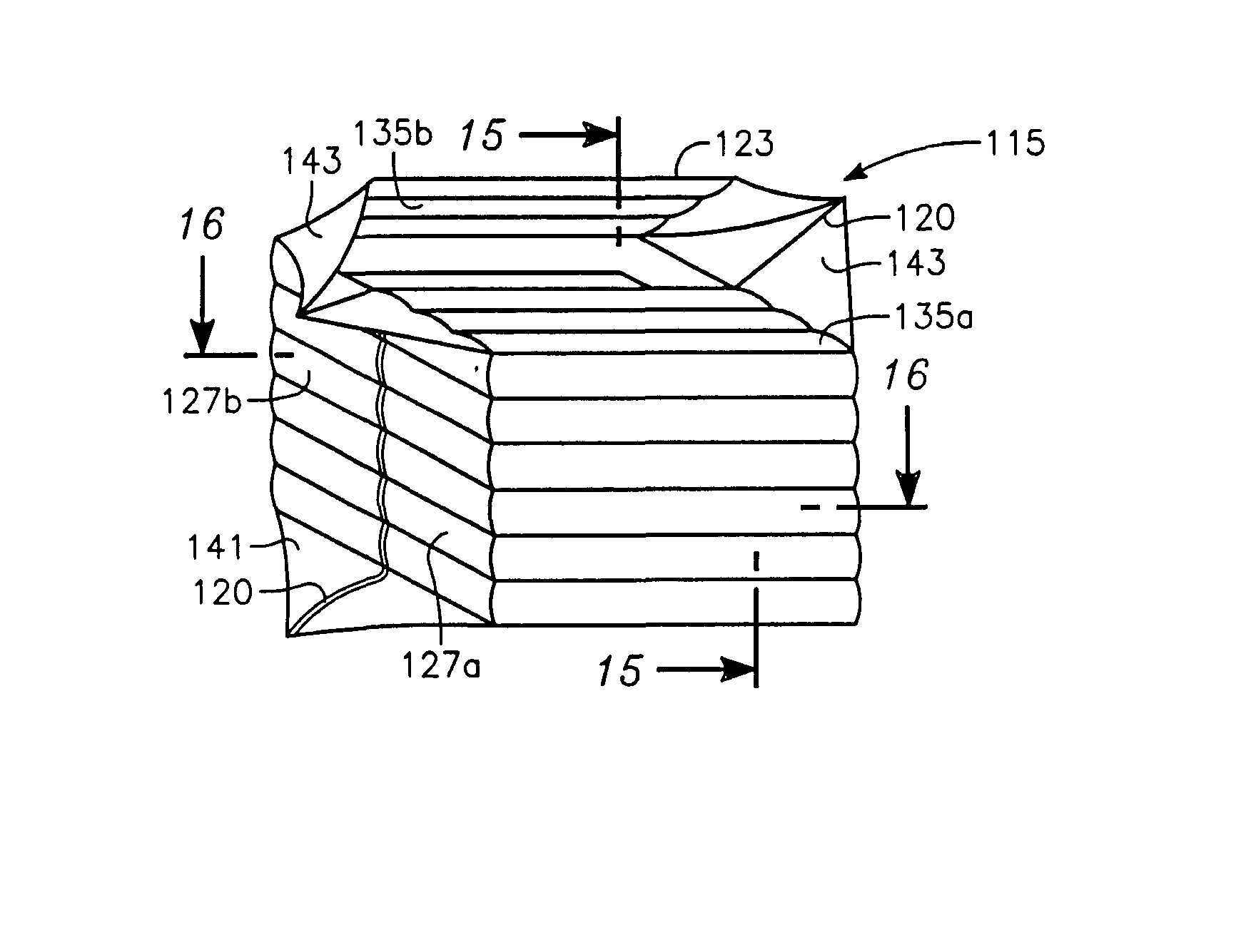
[0028] The use of rf welding enhances the manufacturing efficiencies enjoyed by the use of plastic film layers from which to fabricate the insulated bag. When appropriately pre-folded prior to welding, the plastic film layers and the detailed rf welding pattern jointly cooperate to minimize the number of welding passes required. Bag formation with an asymmetrical welding pattern requires two separate passes, with the second to secure the side panels together, forming the boxed ends.
[0029] Alternatively, the use of a symmetrical, single-pass welding pattern permits the formation of an enclosed bag, including all side sealing seams, and a double-flap instead of a single-flap enclosure lid. The inflatable portion of a single welding pass design is defined by a seam pattern that does not encompass the entire area of the opposing plastic film layers. Adjacent to the symmetrically-formed container floor portion are a pair of uninflated floor gussets. Upon opening the interior portions prior to receipt of the cargo to be shipped, the bottom gussets form a liquid reservoir suitable for receiving and holding any liquids as might drain from the cargo area. Such liquid drainage might be given off by the cargo itself, or result from melt water from the cooling ice. Removal of such liquids from immediate contact with the shipped cargo reduces spoilage and extends the shipping life of the cargo.

Problems solved by technology

Such surface transportation is relatively slow, and the shipped goods must have a correspondingly long shelf life.
However, many temperature-sensitive products, such as perishable foodstuffs, are time-sensitive as well.
While providing satisfactory insulation qualities as well as being light in weight, EPS also presents several negative characteristics to the shipping industry.
EPS"s poor volume efficiency increases shipment costs when transporting the empty containers to the location of their use, as well as causing increased warehousing costs when stored in inventory prior to use.
While providing reasonable protection from shock impacts during transit, EPS has poor resistance to the application of puncture and shear-loading.
EPS easily fractures, requiring the use of an additional plastic liner bag when shipping products with a liquid component, such as ice-chilled, fresh seafood.
The lack of such an additional plastic liner risks liquid leakage from the EPS container during shipment, and the resultant expensive damage to aircraft cargo holds or other corrosion-sensitive shipping environments.
Relying on the property of shiny, metalized coatings to reflectively radiate heat energy, such products have found only marginal success as insulated packaging.
Although reducing warehousing and breakage expenses, as well as enjoying lower manufacturing costs, many shippers have determined that such radiant bags do not control temperatures over a sufficiently long period of time.

Method used


Image

  • Inflatable insulating liners including phase change material
  • Inflatable insulating liners including phase change material
  • Inflatable insulating liners including phase change material

Examples


Embodiment Construction

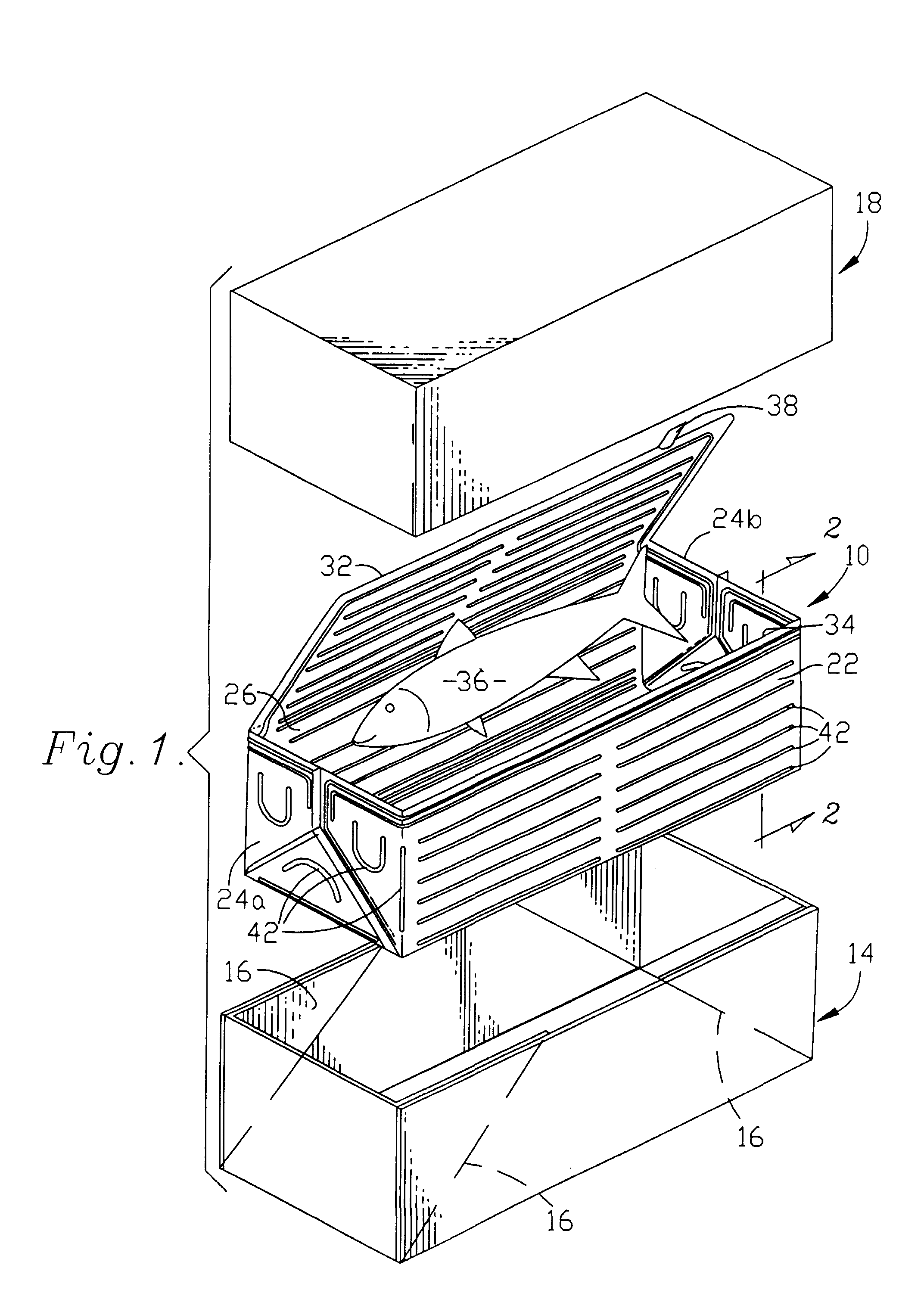
[0032] Reference is now made to the drawings wherein like numerals refer to like parts throughout. An inflatable insulating shipping box liner10 is depicted in Figure1 as received within a transport box bottom 14. A pair of gussets 16 formed at each end of the transport box bottom 14 are preferably provided to minimize the likelihood of any liquid leakage from within the transport box bottom 14.

[0033] A transport box top 18 is received by the transport box bottom 14 in a fully telescoping manner, again minimizing the opportunity for the leakage of liquid from the contents carried within the transport box. Additionally, in a conventional manner the transport box bottom and top 14, 18 are both waxed to preserve their structural integrity against damage caused by liquids that have either leaked from the interior insulating shipping box liner or from liquids wetting an outer surface or surfaces thereof.

[0034] The inflatable insulating shipping box liner 10 includes a front wall 22 a pai...


PUM


Abstract

Abstract of Disclosure An insulating liner is provided having an inflatable, double outer layer defining an interior container space for thermally-sensitive cargo. A phase change material layer is formed upon or carried by a baffle material lying within the inflated layer. The multiple layers forming the insulating liner are attached to one-another in a series of inflation seals that form a plurality of interconnected inflatable chambers which, when inflated, provide structural definition to the interior containment space.

Description

Cross Reference to Related Applications[0001] This application is a continuation-in-part of U.S. Application No. 09 / 156,208, filed September 17, 1998.Background of InventionField of the Invention[0002] The present invention relates to thermally-insulated shipping containers and, more particularly, to shipping containers that are selectively inflatable. More specifically, the present invention relates to a pair of film layers having opposed reflective surfaces, and an optionally-interposed film baffle layer, that together define an inflatable envelope in the form of a flexible insulating bag.Description of the Prior Art[0003] In the transportation and distribution of products, both the product and the package define the "shipping environment". While the corrugated fiberboard boxes, steel drums, wooden crates, and pallets have not changed significantly over the pastyears, the shipping requirements of the products have changed with each new generation of both product and shipping techn...

Claims


Application Information

Patent Timeline
IPC IPC(8): B65D81/05B65D81/38F25D3/08
CPCB65D81/052B65D81/3895F25D3/08F25D2331/804F25D2303/08222F25D2323/061F25D2323/062F25D2303/0822
Inventor MALONE , THOMAS G.MCGRAW , JOHN J.MCKINNEY , DAVID B.
Owner CARGO TECH
Learn More