Method for using field emitter arrays in chemical and biological hazard mitigation and remediation

a technology of emitter array and emitter array, which is applied in the field of field emitter array for chemical and biological hazards mitigation and remediation, can solve the problems of large volume of highly toxic materials already in place that may be vulnerable to terrorist attacks, foreign or domestic, and the use of biological and chemical warfare weapons of mass destruction is the biggest threat to the military and civilian population of the united states and the rest of the world

Inactive Publication Date: 2003-07-24
NORTH TEXAS UNIV OF
View PDF3 Cites 13 Cited by
  • Summary
  • Abstract
  • Description
  • Claims
  • Application Information

AI Technical Summary

Problems solved by technology

One of the biggest threats to the military and civilian populations of the United States and the rest of the world is the use of weapons of mass destruction based on biological and chemical warfare.
However, there is growing concern that terrorists, foreign or domestic, could attack chemical plants producing ammonia (NH.sub.3), chlorine (Cl.sub.2), insecticides, and the like, where there are large volumes of highly toxic materials.
Additionally, there are many manufacturing facilities (for example, manufacturing plants that typically use arsine, germane, diborane, and the like) where there are also large volumes of highly toxic materials already in place that may be vulnerable to terrorist attack.
One of the problems with many of the current schemes for biological warfare defense (BWD) and chemical warfare defense (CWD) is that the defense systems are specific to certain chemicals or pathogens.
Schemes that provide a more general defense such as high temperature catalytic oxidation or radio frequency (RF) plasma oxidation, require a large amount of energy and power, and can produce harmful side-products.
Biological and chemical warfare and / or terrorism and / or accidents are complicated by the fact that the delivery of the biological and / or chemical agents can be as simple as exposure of the pathogens and / or toxins to the atmosphere, resulting in potentially wide dispersal.
Conventional devices are expensive, slow, consume a lot of power, and are bulky.
These devices cannot operate in real-time and are not suitable for battlefield and forward deployment or emergency situations.
Conventional approaches that are fast and that have the potential for real-time operation are extremely agent-specific and can be thwarted by developing new biological and chemical warfare agents.

Method used


Image

  • Method for using field emitter arrays in chemical and biological hazard mitigation and remediation
  • Method for using field emitter arrays in chemical and biological hazard mitigation and remediation
  • Method for using field emitter arrays in chemical and biological hazard mitigation and remediation

Examples


Embodiment Construction

[0024] Illustrative embodiments of the invention are described below. In the interest of clarity, not all features of an actual implementation are described in this specification. It will of course be appreciated that in the development of any such actual embodiment, numerous implementation-specific decisions must be made to achieve the developers' specific goals, such as compliance with system-related and business-related constraints, which will vary from one implementation to another. Moreover, it will be appreciated that such a development effort might be complex and time-consuming, but would nevertheless be a routine undertaking for those of ordinary skill in the art having the benefit of this disclosure.

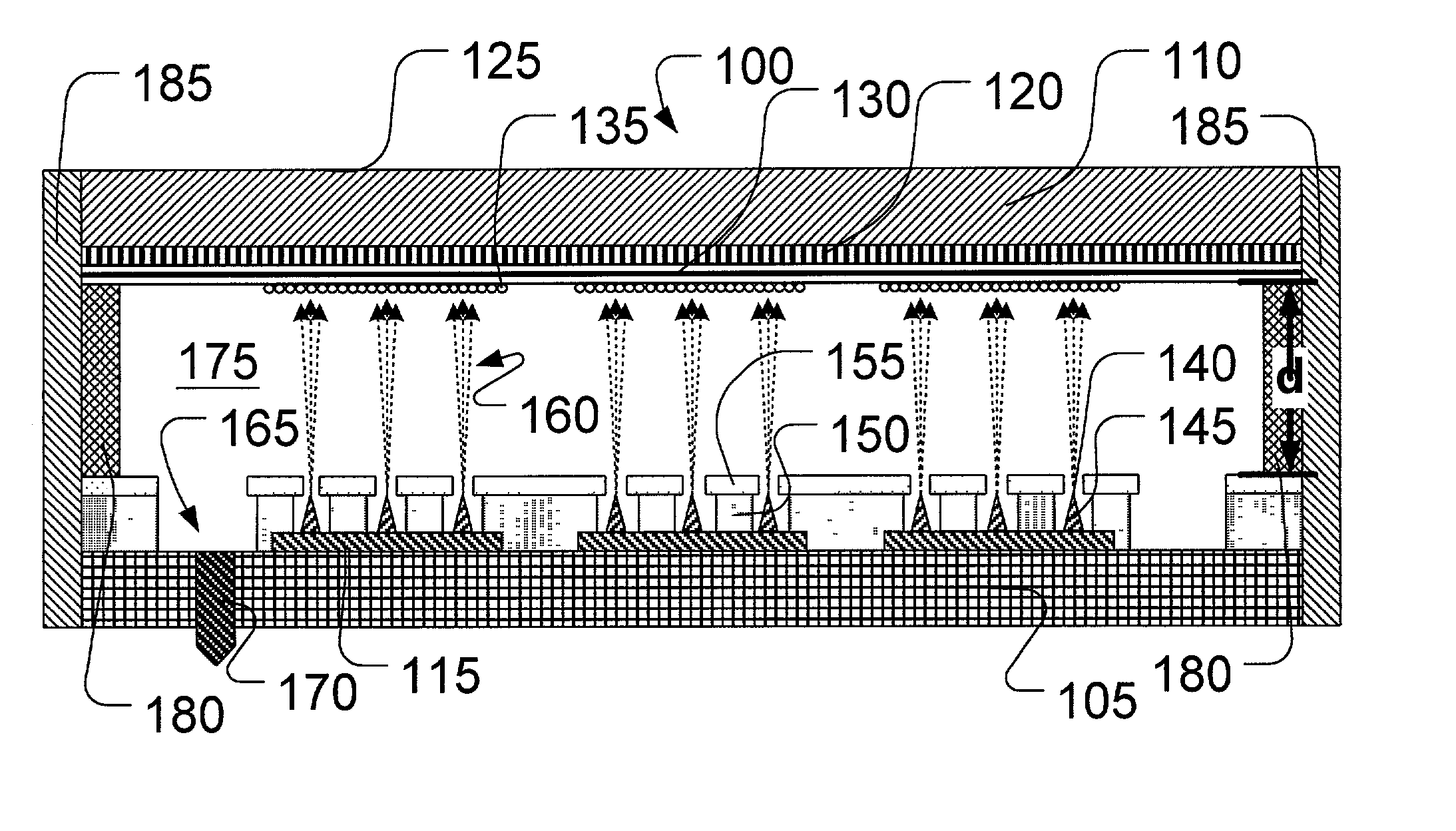
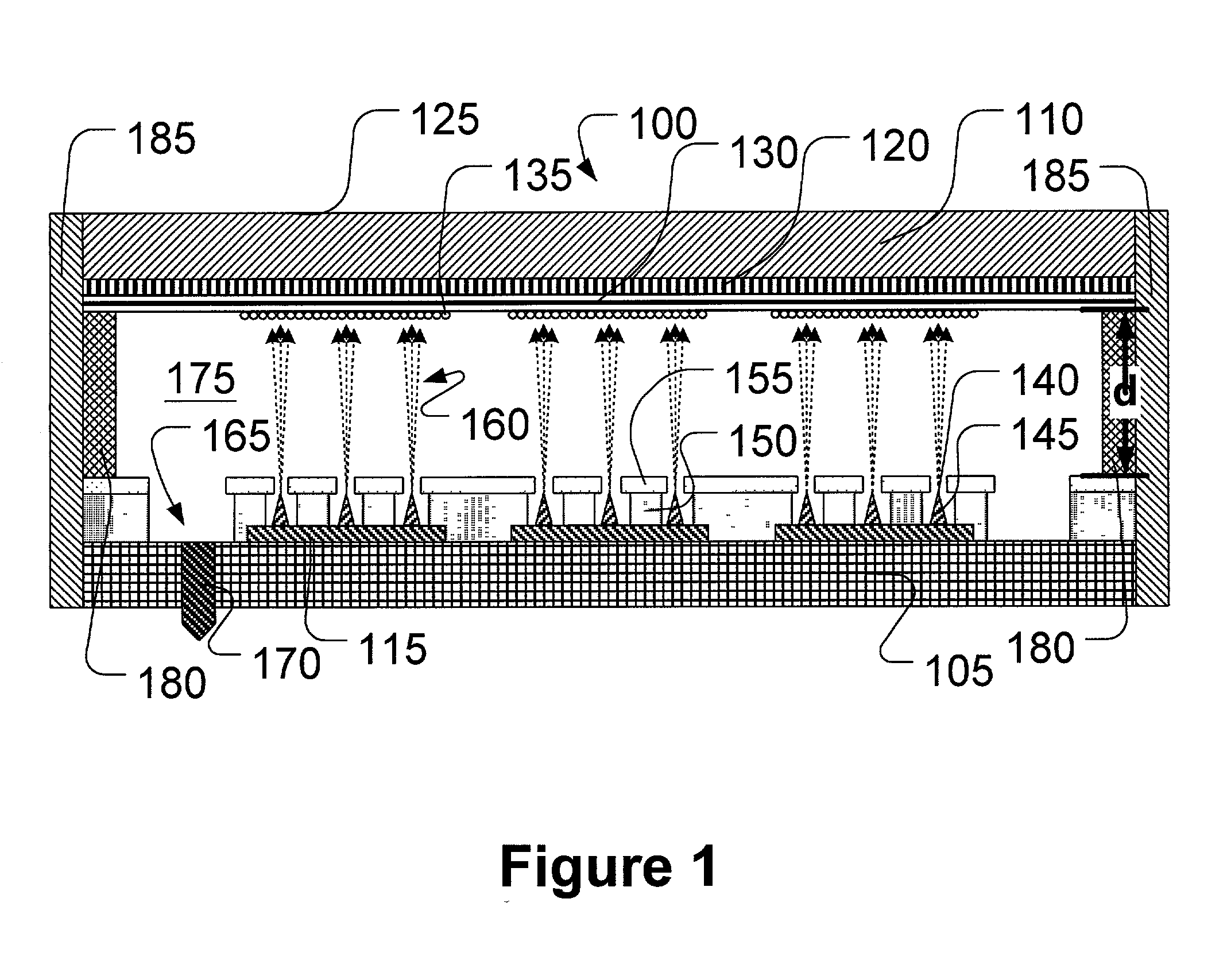
[0025] In various illustrative embodiments of the present invention, high electric fields and electron flux densities generated by field emission arrays (FEAs) are used and employed for biological warfare defense (BWD) and chemical warfare defense (CWD) systems. Additionally, va...


PUM

PropertyMeasurementUnit
electric fieldaaaaaaaaaa
voltagesaaaaaaaaaa
voltagesaaaaaaaaaa

Abstract

A method is provided, the method comprising operating a field emitter array (FEA) to generate at least one of a high electric field and a high electron flux, and exposing the field emitter array (FEA) to at least one gas. The method further comprises generating at least one radical species from the at least one gas exposed to the at least one of the high electric field and the high electron flux.

Description

[0001] 1. Field of the Invention[0002] This invention relates generally to methods of using field ionization devices, and, more particularly, to a method for using field emitter arrays to mitigate and remediate chemical and biological hazards.[0003] 2. Description of the Related Art[0004] One of the biggest threats to the military and civilian populations of the United States and the rest of the world is the use of weapons of mass destruction based on biological and chemical warfare. Research emphasis has been on the detection of biological weapons because of the potentially catastrophic nature of the use of biological weapons. Until recently, there has been less emphasis on chemical weapons because of the large volume of material typically required to pose a major threat. However, there is growing concern that terrorists, foreign or domestic, could attack chemical plants producing ammonia (NH.sub.3), chlorine (Cl.sub.2), insecticides, and the like, where there are large volumes of ...

Claims


Application Information

Patent Timeline
Patent Type & Authority Applications(United States)
IPC IPC(8): A61L2/08A61L2/14A61L9/18A61L9/22B01J19/08G01N27/68G01N33/00
CPCA61L2/08A61L2/14A61L9/18A61L9/22B01J19/085G01N33/0011B01J2219/0803B01J2219/0875B01J2219/0877G01N27/68B01J19/087
Inventor GNADE, BRUCE A.WALLACE, ROBERT M.
Owner NORTH TEXAS UNIV OF
Why Eureka
Try Eureka