

Optimized t-dna transfer and vectors therefor
- Summary
- Abstract
- Description
- Claims
- Application Information
AI Technical Summary
Problems solved by technology
Method used
Image

Examples
example 1
[0150] Transformation of A thaliana (L.) Heynh and Nicotiana tabacum (L.)
[0151] Plasmids pK2L610 (`K` T-DNA vector; De Buck et al. 1998), pSingle gus (`KsbI` T-DNA vector; see below) and pHSB610 (`Hsb` T-DNA vector; De Buck et al. 1999) were used for plant transformation. The vector pSingle gus (`KsbI`) is similar to the vector pHSB610 (`Hsb`) but the Pnos-hpt-3'nos fragment of pHSB610 (`Hsb`) is exchanged for a Pnos-nptlI-3'nos cassette in pSingle gus (`KsbI`). As a selectable marker for plant transformation, the K and KsbI vectors contain the neomycin phosphotransferase II gene (nptlI) and the Hsb vector contains the hygromycin phosphotransferase gene (hpt). A. thaliana was co-transformed with plasmids K and Hsb according to the Agrobacterium-mediated Arabidopsis root transformation method (De Buck et al. 1999, Valvekens et al. 1988). Tobacco (N. tabacum) was transformed with plasmid Ksb according to the Agrobacterium-mediated leaf disc transformation method (Horsch et al. 1985). ...
example 2
[0152] Integration of Vector Backbone Sequences Assessed by PCR
[0153] For PCR analysis, DNA was isolated from leaf material of N. tabacum as described by Jones et al. (1985) and from A. thaliana according to De Neve et al. (1997). To screen the transgenic plants on the integration of vector sequences, different PCR reactions were performed. DNA (100 ng) was incubated with 500 ng of each primer in 1.times. Taq polymerase incubation buffer (Roche Diagnostics, Brussels, Belgium). Two and a half units of Taq polymerase were added to a final volume of 100 .mu.L. Samples were heated to 94.degree. C. for 5 min before PCR. Denaturation was at 94.degree. C. for 1 min. Annealing occurred during 2 min at 57.degree. C., and the extension reaction was at 72.degree. C. for 5 min, while 30 cycli were performed. The primer combinations were chosen so that the presence of at least 100 bp (`RB100` and `LB100` in Tables 1 and 2) or at least 1000 bp (`LB1000` and `RB1000` in Tables 1 and 2) of vector b...
example 3
[0158] Integration of Vector Backbone Sequences Assessed by DNA Gel Blotting
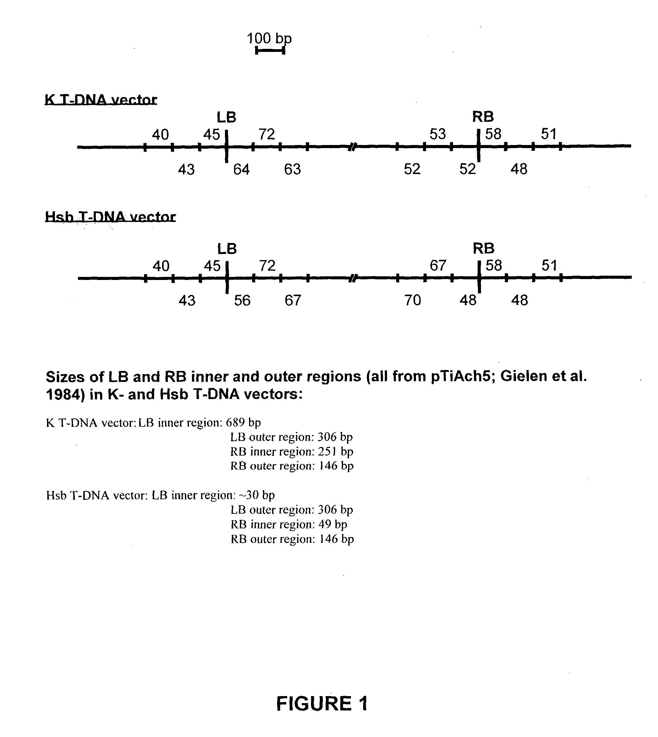
[0159] DNA gel blot analysis was performed essentially according to Maniatis et al. (1982) on approximately 0.6 .mu.g genomic DNA. The restriction sites used (KpnI-SacI) are indicated in FIG. 5A. As probe, the vector sequence of the K plasmid was used after restriction with KpnI and SacI. The non-radioactive "Gene images" random prime labelling module and the "Gene images" CDP Star detection module (Amersham, Aylesburg, UK) were used for the hybridization and the detection, respectively. As outlined in Example 2, linkage of both RB and LB regions to at least a 1000 bp vector backbone fragment of one or both plasmids was observed in different transformants of series 1 (see Table 1). To determine whether the complete binary T-DNA plasmid (T-DNA+vector backbone sequences) is integrated into the genome of these transformants, a DNA gel blot analysis was performed with the K vector sequence as probe. When the who...
PUM
| Property | Measurement | Unit |
|---|---|---|
| Fraction | aaaaa | aaaaa |
| Length | aaaaa | aaaaa |
| Efficiency | aaaaa | aaaaa |
Abstract
Description
Claims
Application Information