Dual piston drag damper for rotary-wing aircraft rotor

a technology of rotary-wing aircraft and dampers, which is applied in the direction of propellers, propulsive elements, water-acting propulsive elements, etc., can solve the problems of high vibration and stress levels in the fuselage, rare phenomena, and waste of weigh

a technology of rotary-wing aircraft and dampers, which is applied in the direction of propellers, propulsive elements, water-acting propulsive elements, etc., can solve the problems of high vibration and stress levels in the fuselage, rare phenomena, and waste of weigh

US20030146343A1Inactive Publication Date: 2003-08-07EUROCOPTER

Image

  • Dual piston drag damper for rotary-wing aircraft rotor
  • Dual piston drag damper for rotary-wing aircraft rotor
  • Dual piston drag damper for rotary-wing aircraft rotor

Examples


Embodiment Construction

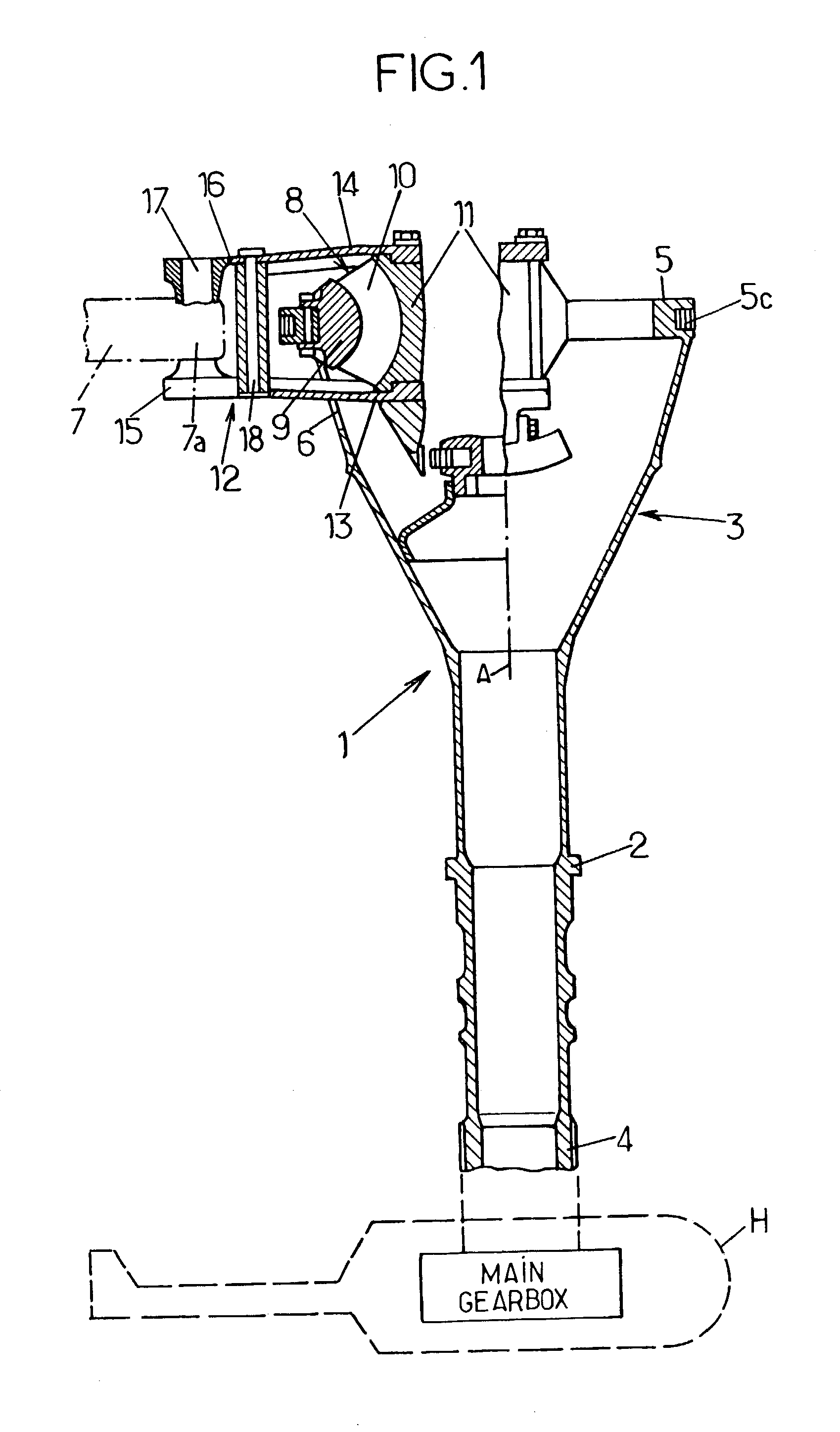
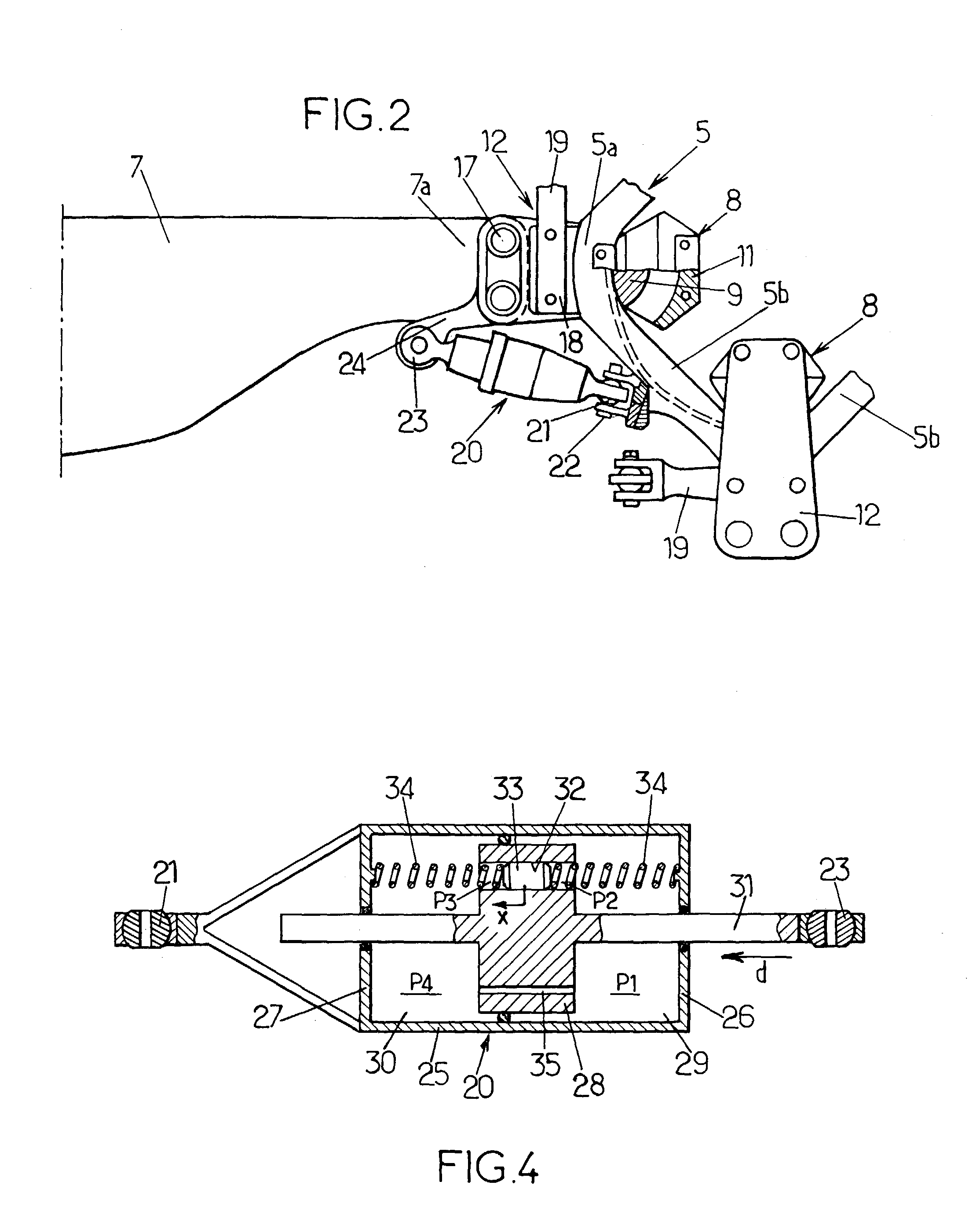
[0068] FIGS. 1 and 2 show schematically the head of a four-bladed helicopter main rotor substantially as described in EP 0 213 016 with reference to FIGS. 4 and 5 of that document, to which reference may advantageously be made for further details.

[0069] It will be recalled that this rotor head comprises a one-piece tubular mast-hub 1, the lower substantially cylindrical part of which forms a mast 2 with a base 4 designed to be connected in rotation to a main gearbox of the helicopter H (shown schematically in phantom outline) to drive the rotor in rotation about the axis A of the mast-hub 1. The latter also comprises an upper part forming a hub 3, which is an extension of the mast 2 and has the general external shape substantially of a truncated cone hollowed out at the end opposite to the mast 2 as far as a reinforcement ring 5 which constitutes the upper free end, thickened locally on its periphery, of the hub 3. Radial (relative to axis A) openings 6, identical and equal in numbe...


PUM


Abstract

A drag damper for use on a rotary wing aircraft rotor comprises a body defining two variable volume chambers linked by a piston. The chambers are filled with fluid and are connected by a restriction port (35) and by a channel (32) of larger cross-section than the restriction port. A secondary piston slidable and pressure-tight piston is fitted in the channel and loaded by an elastic bias (34). The equivalent mass of this secondary piston (33) and of the fluid which it displaces, and the stiffness of the elastic bias (34) are such that the secondary piston is resonant in the channel (32) at the rotation frequency of the rotor, to filter the dynamic component at this frequency of stresses applied to the damper (20). Furthermore at the natural drag frequency of the corresponding blade, the elastic bias substantially blocks the secondary piston (33) in its channel (32), and the flow of fluid between the chambers (29, 30) of the damper (20) takes place mainly via the restriction port (35) calibrated to provide substantial damping at this frequency.

Description

[0001] The invention relates to a drag damper for a rotary-wing aircraft rotor comprising a hub and at least two blades each of which is connected to the hub by a corresponding connection device. The drag damper is intended for fitting between two elements, one of which is a flapping mass comprising one of the blades and the corresponding connection device, and the other element is one of the hub (in the conventional configuration) and an adjacent flapping mass on the rotor (in the so-called inter-blade configuration). In use, the drag damper will dampen the relative angular drag movements between said two elements, namely: in the first case (conventional configuration), the angular drag movements of said flapping mass relative to the hub, i.e. the angular deflections of the blade, and more generally of the corresponding flapping mass, about its drag axis, which is substantially parallel to the axis of rotation of the rotor; and in the second case (inter-blade configuration), the re...

Claims


Application Information

Patent Timeline
07 Aug 2003
Publication
US20030146343A1
IPC
B64C27/35; B64C27/51; F16F9/20; F16F9/504
CPC
B64C27/35; F16F9/504; F16F9/20; B64C27/51
Inventors
ZOPPITELLI, ELIO; LEGENDRE, PHILIPPE