Capillary array unit electrophoretic device comprising the same

Inactive Publication Date: 2003-08-21
HITACHI LTD
View PDF8 Cites 13 Cited by
  • Summary
  • Abstract
  • Description
  • Claims
  • Application Information

AI Technical Summary

Benefits of technology

0004] The object of the present invention is to provide a capillary array characterize

Problems solved by technology

Hei 09-096623, this reflected light is detected by the light receiving optical system to become one of the causes for increase of the background light, resulting in deterioration of the detectio

Method used


Image

  • Capillary array unit electrophoretic device comprising the same
  • Capillary array unit electrophoretic device comprising the same
  • Capillary array unit electrophoretic device comprising the same

Examples


embodiment 1

[0028] [Embodiment 1]

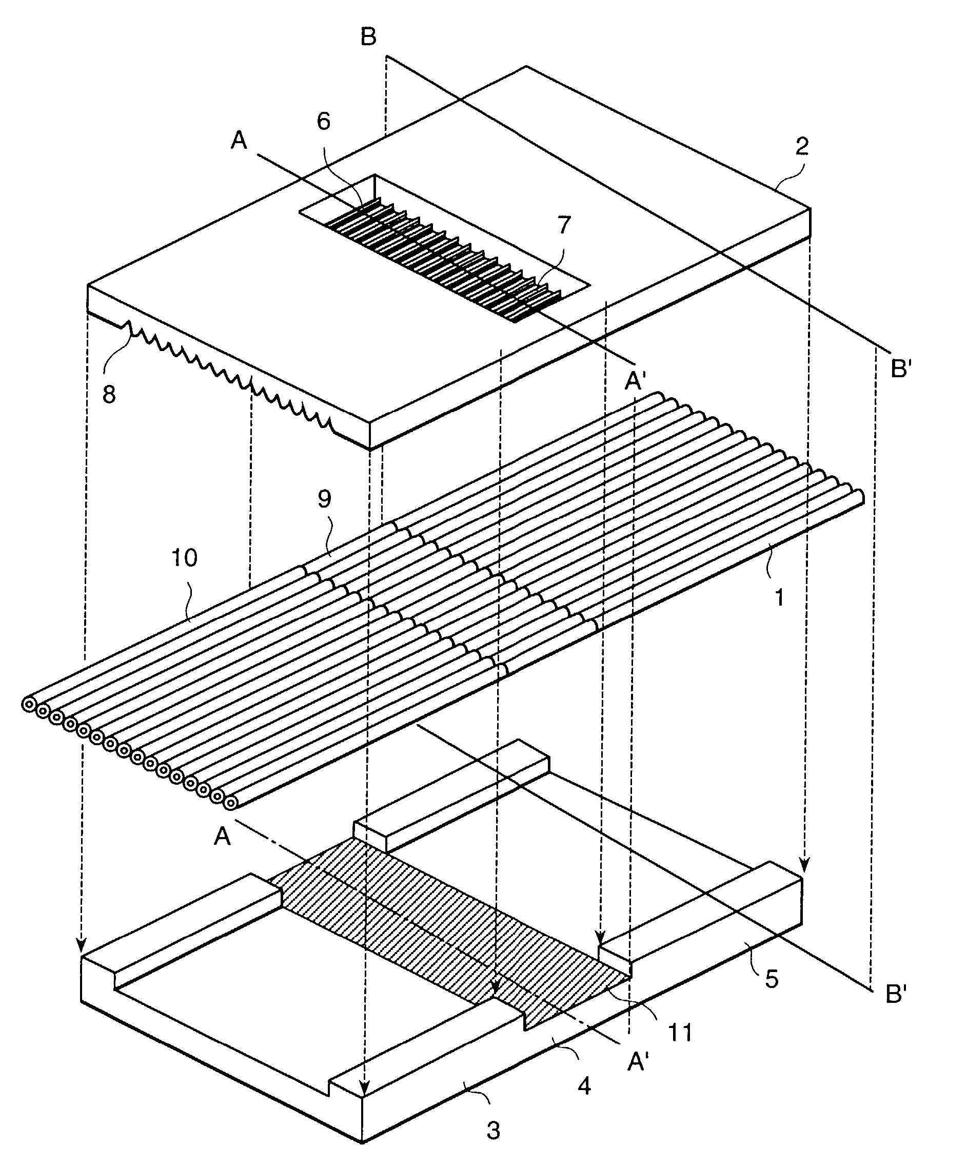
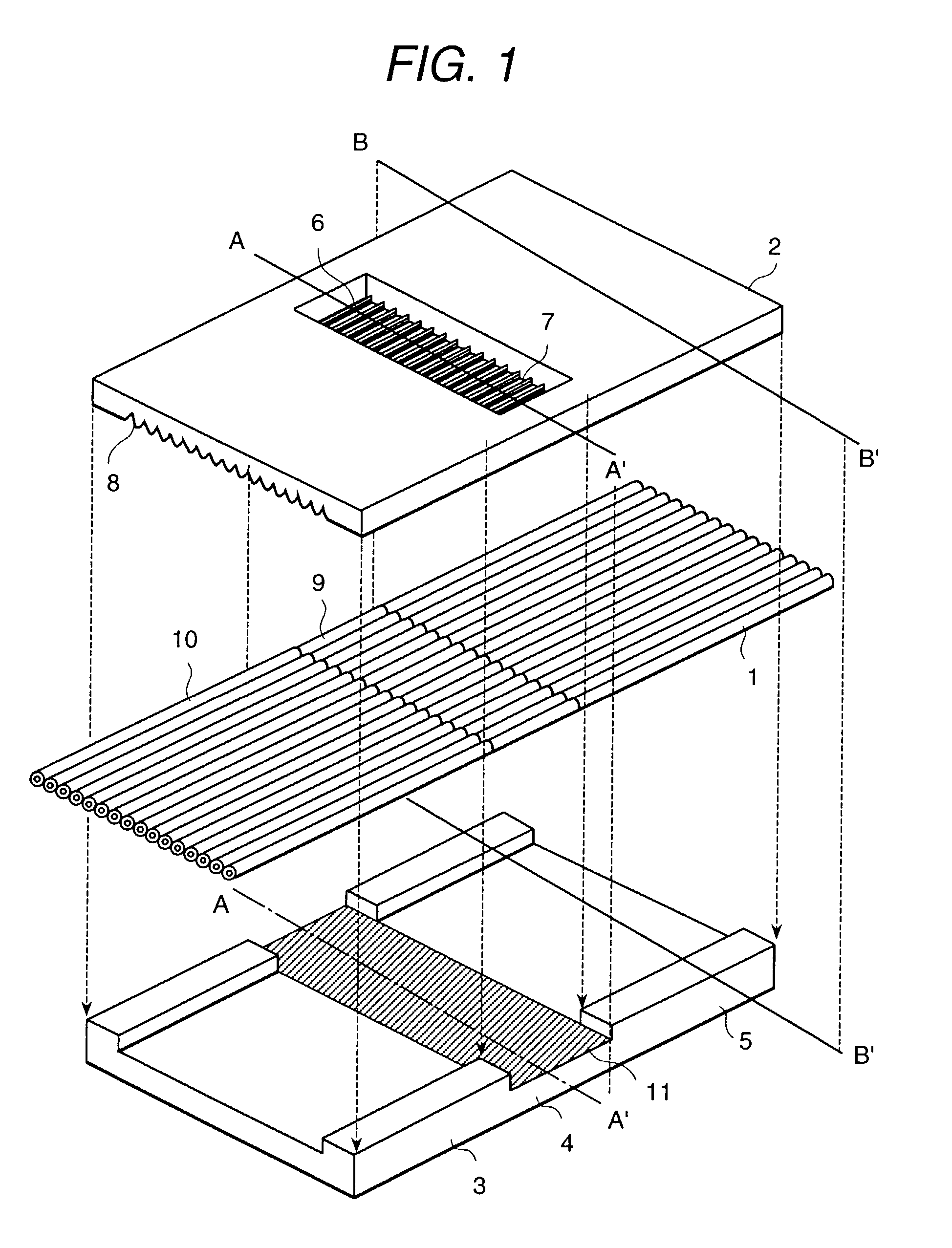
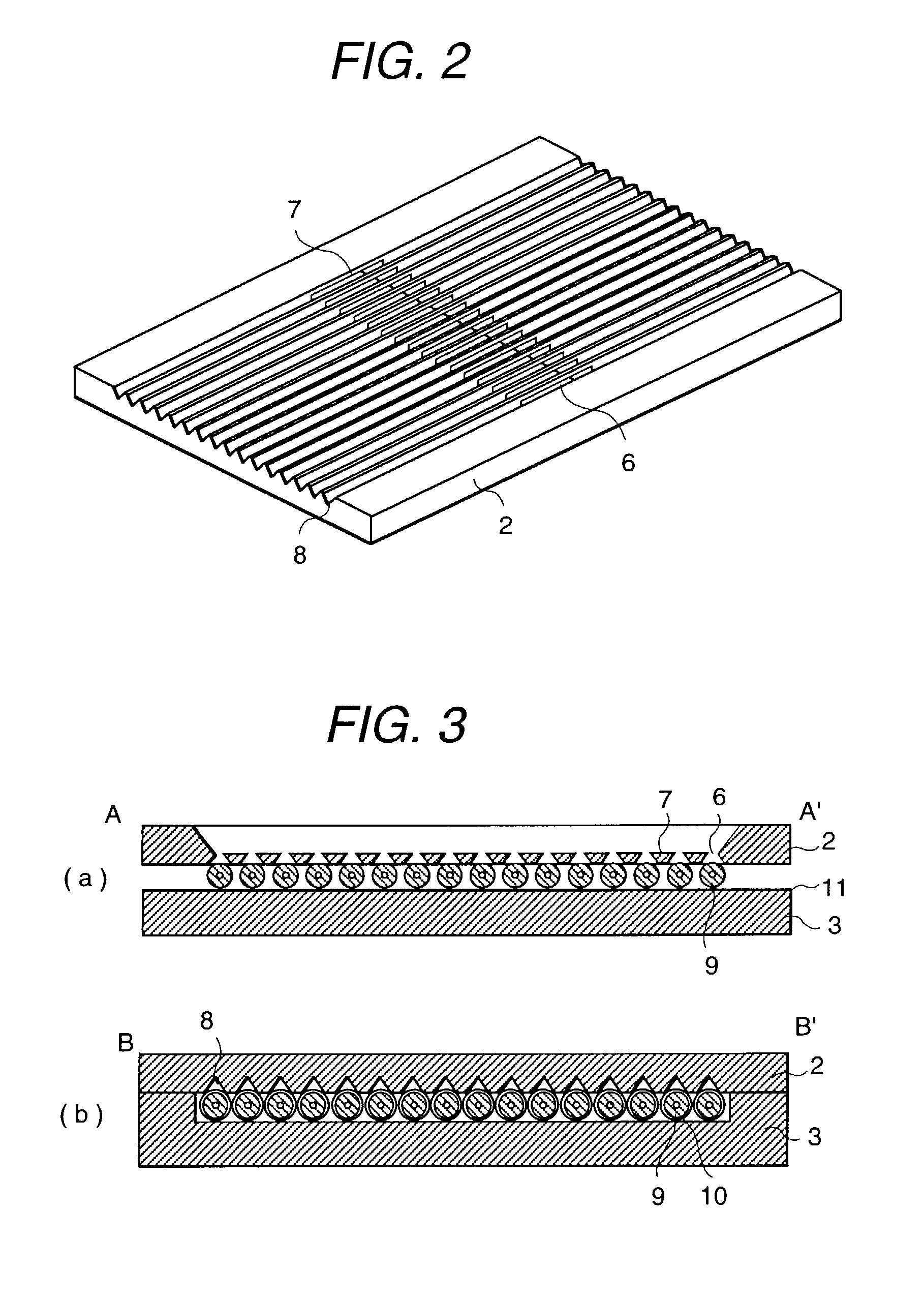
[0029] FIG. 1 is a configuration drawing representing the window unit as a first embodiment of the present invention. The window unit comprises a capillary 1, window substrate 2, glass substrate 3, etc. as shown in FIG. 1. FIG. 2 is an explanatory diagram of the window substrate 2 of FIG. 1 viewed from a different direction. FIG. 3 is cross sectional views taken long lines A-A' and B-B' of the window unit of FIG. 1. FIG. 3(a) and FIG. 3(b) correspond to a laser irradiated region 4 and non-irradiated region 5 of FIG. 1, respectively.

[0030] As shown in FIG. 1, the window substrate 2 is a silicon substrate. Sixteen openings 6 passed by light are formed in a straight line at the same dimensional interval as that for the arrangement of the capillaries 1, using silicon anisotropic etching technology characterized by excellent processing accuracy. V-grooves 8 having a V-like configuration in cross section are formed on the front and back of the openings 6 corresponding...

embodiment 2

[0033] [Embodiment 2]

[0034] FIG. 5 is a configuration drawing representing the window unit as a second embodiment of the present invention. Its difference from the first embodiment is that a transparent substrate 12 such as a glass substrate for transmitting light is used as a window substrate, and the low light-transmittance member 13 is created, for example, by vapor deposition. The first embodiment is configured to have an opening 6, but the present embodiment uses a non-penetration window 14. This non-penetration window 14 is formed by removing the low light-transmittance member 13 by etching to ensure that it is formed at the same interval as that of the arranged capillaries 1. A non-penetration window frame formed cut-off area 15 partitions this non-penetration window 14, thereby reducing transmission of light through the non-penetration window frame formed cut-off area 15, and minimizing the background light. In the window unit as the second embodiment, almost the same effect...

embodiment 3

[0036] [Embodiment 3]

[0037] FIG. 7 is a configuration drawing representing the window unit as a third embodiment of the present invention. The difference from the aforementioned embodiment 2 is that non-penetration windows 14 are formed on the transparent substrate 12 such as a glass substrate for transmitting light as window substrate, and V-grooves 8 having a V-like configuration in cross section are formed on the front and back of the non-penetration window 14 in order to position the capillary 1 sequence. In the window unit as the third embodiment, the same effects as those of the second embodiment can be obtained. Further, V-grooves 8 are provided to position the sequence of capillaries 1, thereby reducing the misalignment of the capillaries and improving the workability.

[0038] FIG. 7 shows the non-penetration window 14 configured in a rectangular form, but the form is not restricted to a rectangular one. The number of non-penetration windows 14 is not limited to ten. The same ...


PUM


Abstract

A capillary array comprising multiple capillaries and two holding substrates for arranging the aforementioned multiple capillaries in a substantially plane surface by sandwiching at least some of these capillaries mutually. One of the holding substrates has a detection window for transmitting the detected light emitted by a test sample by irradiation of light. Especially, this detection window comprises multiple light transmission areas provided to correspond to each capillary to transmit the detected light, and light cut-off areas provided between these light transmission areas to cut off the detected light. These light cut-off areas cut off light reflected from the surface of capillaries and hence improve the SN ratio, thereby ensuring high-precision detection.

Description

[0001] The present invention relates to a capillary array electrophoresis apparatus for separating and analyzing such a sample as DNA and protein.[0002] Analysis of such a sample as DNA and protein is growing in importance in recently years, and this requires a DNA sequencer to provide a higher speed and greater throughput. One of the examples is found in a capillary array electrophoresis apparatus having multiple capillaries arranged in a plane surface. The capillary array electrophoresis apparatus basically comprises a capillary array, an excitation optical system consisting of a laser light source and the like, and a light receiving optical system for detecting fluorescent light. The capillary array consists of capillaries arranged in a plane surface. Laser light is applied to the capillary filled with the sample (fluorescent sample) labeled with fluorophore in the direction parallel to the capillary arranged surface, and laser light is condensed by a lens-like function of the ca...

Claims


Application Information

Patent Timeline
IPC IPC(8): G01N27/447
CPCG01N27/44782G01N27/44721
Inventor MORIOKA, TOMONARISHIMIZU, YASUSHIUGAI, SEIICHIKITA, TOSHIAKITSUKADA, KIYOSHI
Owner HITACHI LTD
Why Eureka
Try Eureka