Method for measuring orientation of paper fibers and apparatus for measuring orientation of paper fibers

a technology of paper fibers and orientation, applied in the direction of polarisation-affecting properties, instruments, material analysis, etc., can solve the problems of unable to detect the maximum value and the minimum value at one and the same position on the paper web, and the accommodative method and apparatus,

Inactive Publication Date: 2003-08-21
NIPPON PAPER IND CO LTD
View PDF8 Cites 30 Cited by
  • Summary
  • Abstract
  • Description
  • Claims
  • Application Information

AI Technical Summary

Problems solved by technology

However, such method and apparatus have been accompanied with various problems as follow.
First, it may be impossible to detect the maximum value and the minimum value at one and same position on the paper web being made since the web is running during rotation of the detector.
Regrettably, the fiber orientation more or less depend on the particular position on the paper web being made and therefore it may be impossible for this apparatus of well known art to detect the fiber orientation being variable as the paper web runs.
Thus, it may be thus substantially impossible to on-line determine the fiber orientation of the web running through the paper making machine.
In other words, it may be impossible to reflect the result of measurement instantaneously in paper being made and thereby to obtain paper having desired fiber orientation.
Consequently, it is difficult to maintain the distance between the paper web and the ima...

Method used


Image

  • Method for measuring orientation of paper fibers and apparatus for measuring orientation of paper fibers
  • Method for measuring orientation of paper fibers and apparatus for measuring orientation of paper fibers
  • Method for measuring orientation of paper fibers and apparatus for measuring orientation of paper fibers

Examples


Embodiment Construction

[0044] The method and the apparatus for measurement of paper fiber orientation according to the present invention will be more fully understood from the description of the preferred embodiments given hereunder in reference with the accompanying drawings.

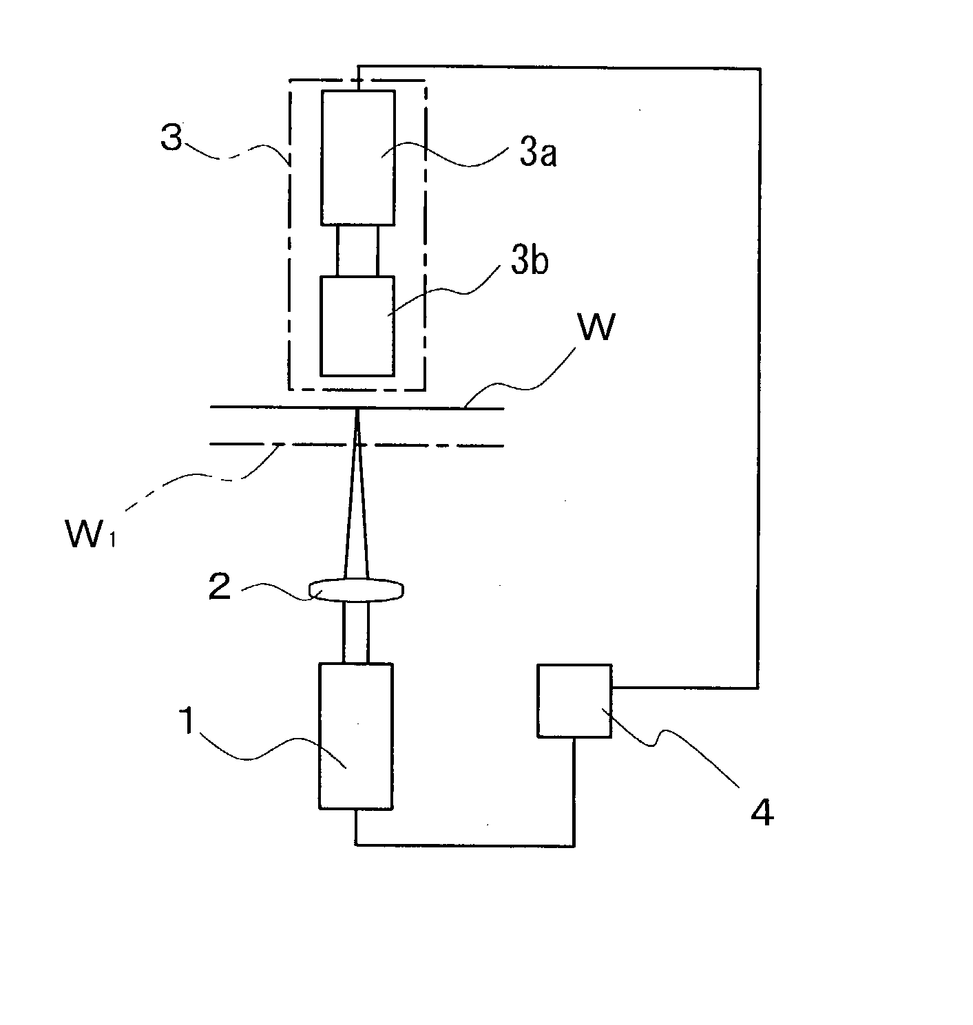
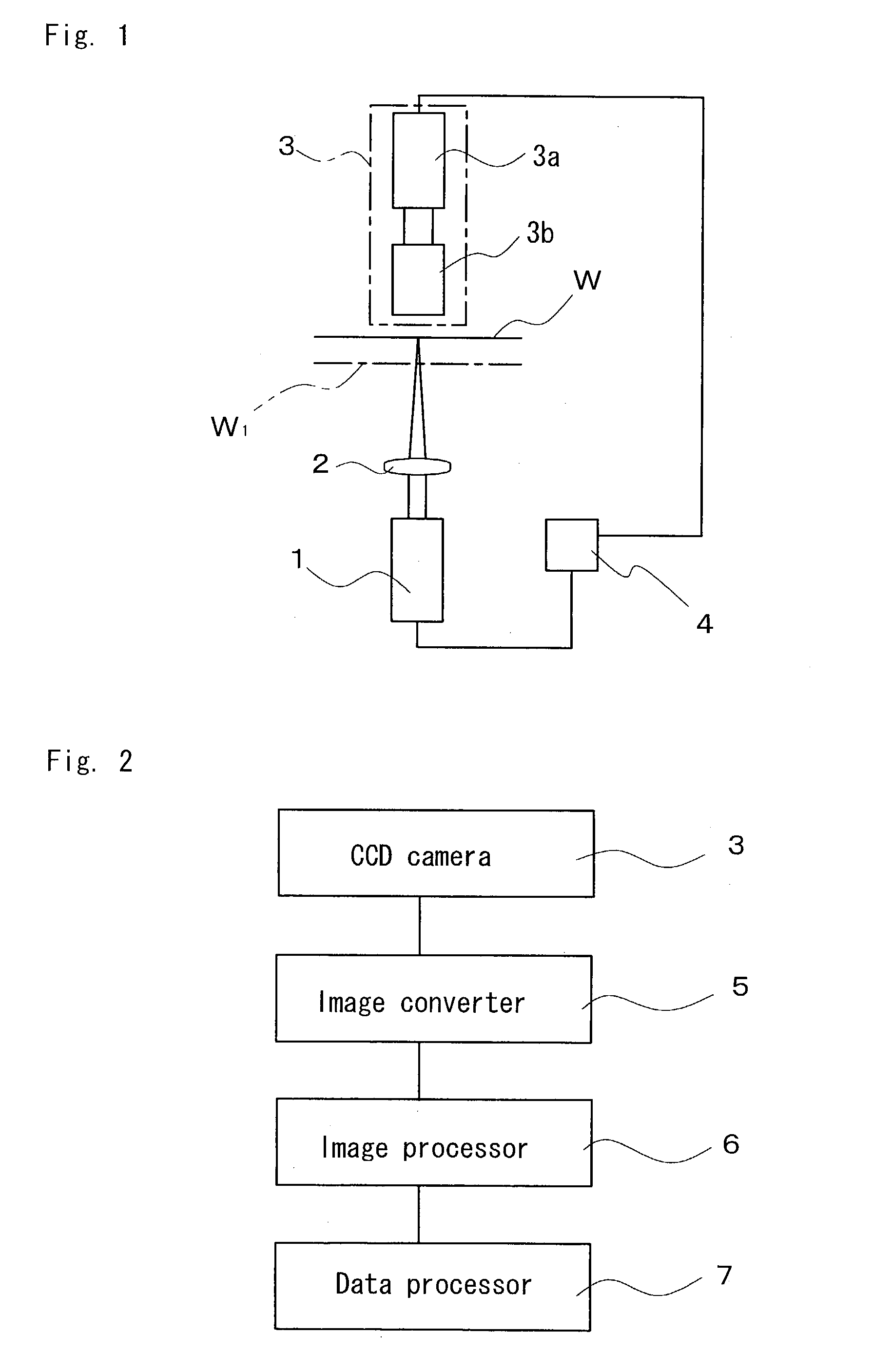
[0045] FIG. 1 is a block diagram schematically illustrating the paper fiber orientation measuring apparatus according to the invention. A pulse laser source 1 serving as projector means is provided to face one surface of paper web W of which the fiber orientation are to be determined so that the paper web W may be irradiated with a laser beam emitted from this pulse laser source 1. The laser beam emitted from this pulse laser source 1 is substantially circular unpolarized laser beam. In front of the pulse laser source 1, a condenser lens 2 is located in front of the pulse laser source 1 to condense the laser beam emitted from this source 1 and thereby to adjust a diameter of the laser beam appropriately to enter the paper web W.

[0046...


PUM


Abstract

The present invention aims to provide method and apparatus to measure paper fiber orientation adapted to measure fiber orientation in this paper from an image to be measured formed by light beam transmitted through paper on the paper side opposite to the incident side thereof improved so that the fiber orientation in this paper being running through a paper making machine can be reliably on-line measured. Paper web (W) is irradiated practically at a right angle thereto with light beam emitted from a pulse laser source (1) and unpolarized through a condenser lens (2) and an image to be measured formed on a surface of the paper web (W) opposite to its incident surface is picked up by a CCD camera (3). An image pick-up optical system (3b) of the CCD camera (3) uses an extra depth-of-field lens. The image picked up in this manner is then image processed for elliptic approximation. Then a fiber orientation angle relative to a major axis of the obtained ellipse and a magnitude of fiber orientation based on a difference or a ratio between the major and minor axes of this ellipse are calculated. Pick-up by the CCD camera (3) may be carried out at predetermined periods and with an appropriate pulse width to pick up a target image as if the paper web (W) is in stationary state.

Description

[0001] The present invention relates to method and apparatus for measurement of fiber orientation and particularly to such method and apparatus suitable for measurement of fiber orientation in paper during a process of paper making.DESCRIPTION OF THE RELATED ART[0002] To make paper of high quality, it is essential to determine paper quality as well as fiber orientation of the paper obtained as finished product. Various apparatuses for this purpose have already been proposed. German Patent Application Disclosure Gazette No. 34134558A1 discloses a fiber orientation measuring apparatus of this type adapted to detect a differential magnitude of two extreme values of fiber orientation, using a diffusion effect (i.e., light guide effect). This fiber orientation measuring apparatus of well known art non-contact detects any extreme fiber orientation appearing in roll paper, particularly running roll paper and / or detects a differential magnitude of two such extreme fiber orientations. In thi...

Claims


Application Information

Patent Timeline
IPC IPC(8): G01N21/17G01N21/21G01N21/86G01N33/34
CPCG01N21/17G01N21/211G01N2021/8681G01N33/34G01N33/346G01N21/86
Inventor KAZUHIKO, FUKUOKATODOROKI, HIDENOBUNURUKI, YUTAKAABE, YUJI
Owner NIPPON PAPER IND CO LTD
Why Eureka
Try Eureka