Consecutively wound or stacked battery cells

a battery cell and stacked technology, applied in the field of batteries, can solve the problems of affecting the efficiency of battery cells,

Inactive Publication Date: 2003-08-28
LITHIUM POWER TECH
View PDF9 Cites 60 Cited by
  • Summary
  • Abstract
  • Description
  • Claims
  • Application Information

AI Technical Summary

Benefits of technology

0012] The problems noted above are solved in large part by a consecutively wound or stacked battery system in which a plurality of devices are constructed by consecutively winding those devices on top of each other to produce a multiple device system in a single integral unit. The multiple devices could be battery cells, fuel cells, capacitors and the like. More particularly, the preferred embodiments are directed to consecutively wound lithium battery cells having solid polymer electrolyte, each battery cell separated by an insulating layer that extends beyond an anode or cathode layer in each of the battery cells. Once the requisite number of cells are wound into the consecutively wound system, the axial or rolled ends of the consecutively wound system are preferably coated or shooped with a conductive material. A portion of this conductive material is preferably removed by brushing such that the conductive material cannot provide continuity from one cell to another. Thus, each battery cell in the consecutively wound unit is electrically isolated from other battery cells. By the use of external jumpers between the battery cells at the shooping, the plurality of consecutively wound battery cells can be connected in any series or parallel fashion to produce desired voltages and currents.
0013] In an alternative, but related, embodiment of the preferred embodiments, the consecutively wound battery system is wound on a cylindrical mandrel having a large (for example, two to five foot) diameter mandrel. The process is continued as described with respect to the previous paragraph; however, once the winding is complete the consecutively wound battery is cut on one side along the radial plane intersecting an axis of the winding. The cut consecutively wound battery is then laid flat to produce a substantially rectangular shaped stacked battery system. While it is possible to use the stacked battery system directly, preferably the stacked battery is cut along its width to produce a desired length, and thus a desired capacity. Additionally, a substantially rectangular shaped battery may also be cut, either during the winding process or thereafter, to a particular width as a further adjustment of the capacity. One consecutively wound battery system cut to become a stacked battery may produce many battery systems having varying voltages (by coupling in parallel or series the plurality of batteries in the stack) and current capacities (by cutting to produce a particular length, width or both) as needed or required.
0014] The disclosed devices and methods comprise a combination of features and advantages which enable it to overcome the deficiencies of the prior art devices. The various characteristics described above, as well as other features, will be readily apparent to those skilled in the art upon reading the following detailed description, and by referring to the accompanying drawings.

Problems solved by technology

Whether circular or elliptical, related art battery windings are only a single cell, and therefore only operate at a single voltage; however, many modem electronic devices need multiple voltages to operate correctly.
However, battery systems with multiple voltages achieved by connecting a plurality of individual battery cells are expensive to build.
However, there are still multiple battery cells, and possibly capacitors, within the battery pack.
As can be appreciated from this description, assembling battery packs in this manner is very labor intensive, thus contributing to the expense of construction.
While it is possible to build capacitors that share dielectric material, the electrolyte of different batteries may not be shared between battery cells.
A second, but related, problem faced by the battery industry is providing batteries of correct amperage capacity.
That is, while any battery may have at its output terminals a necessary voltage, the battery may not have the amperage capacity to hold the rated terminal voltage at required amperage demands.
This procedure too is labor intensive, and requires battery manufacturers to have significant stocks of batteries of varying capacity to meet possible demand.

Method used


Image

  • Consecutively wound or stacked battery cells
  • Consecutively wound or stacked battery cells
  • Consecutively wound or stacked battery cells

Examples


Embodiment Construction

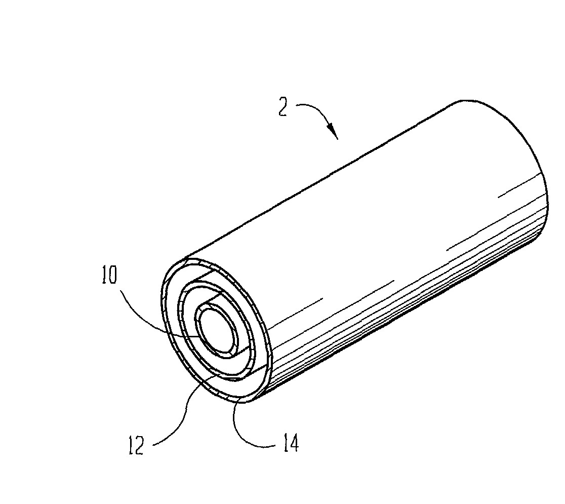
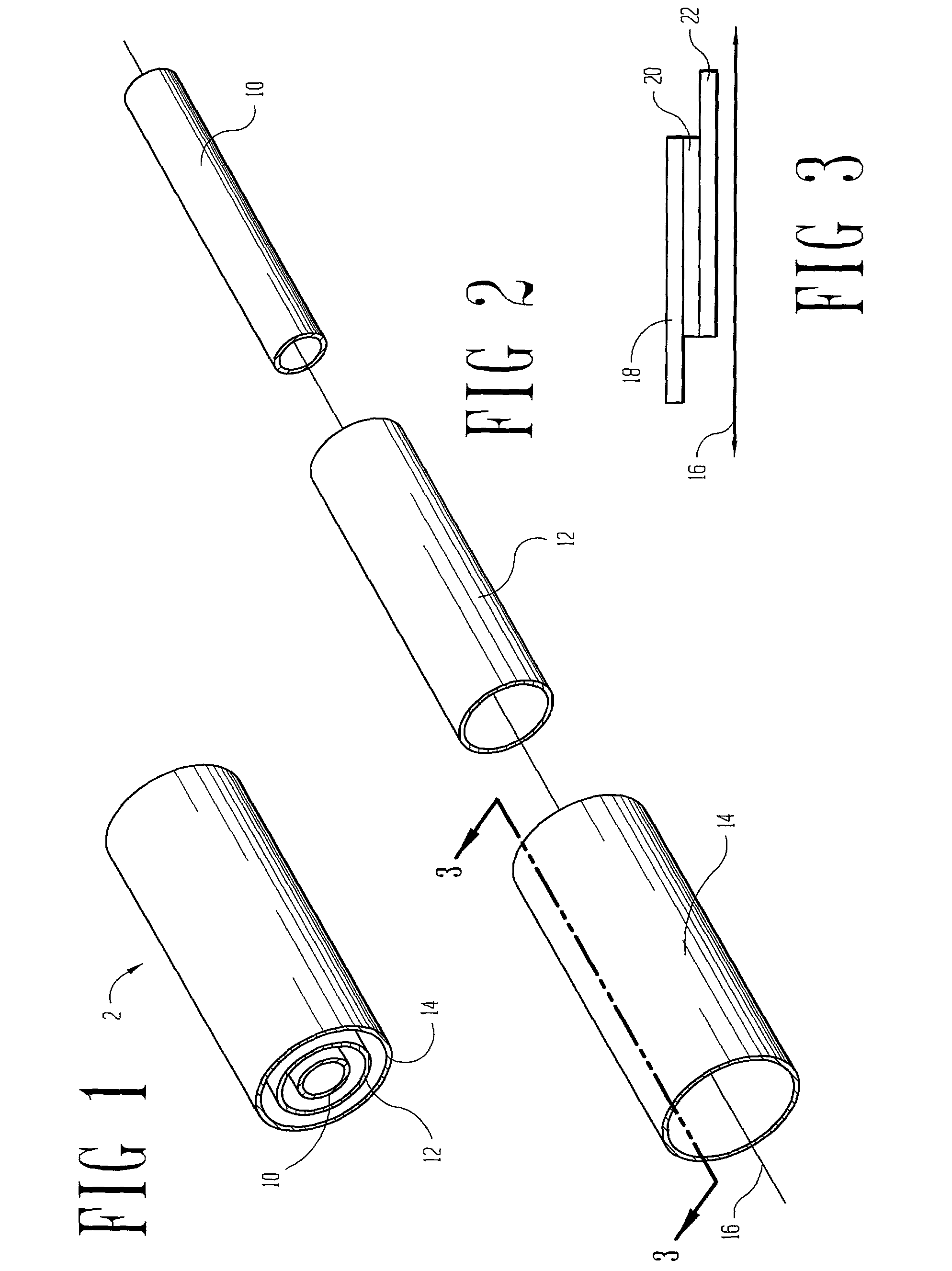
[0012] The problems noted above are solved in large part by a consecutively wound or stacked battery system in which a plurality of devices are constructed by consecutively winding those devices on top of each other to produce a multiple device system in a single integral unit. The multiple devices could be battery cells, fuel cells, capacitors and the like. More particularly, the preferred embodiments are directed to consecutively wound lithium battery cells having solid polymer electrolyte, each battery cell separated by an insulating layer that extends beyond an anode or cathode layer in each of the battery cells. Once the requisite number of cells are wound into the consecutively wound system, the axial or rolled ends of the consecutively wound system are preferably coated or shooped with a conductive material. A portion of this conductive material is preferably removed by brushing such that the conductive material cannot provide continuity from one cell to another. Thus, each b...


PUM

PropertyMeasurementUnit
diameteraaaaaaaaaa
diameteraaaaaaaaaa
diameteraaaaaaaaaa

Abstract

The specification discloses a consecutively wound or stacked battery system and a method for making these devices. In one aspect, battery cells are wound consecutively, separated by insulating layers, to form an integral battery system capable of producing multiple voltages. In a second, but related, aspect, multiple battery cells are wound consecutively on a large diameter mandrel, cut in a radial plane, and laid flat to form stacked battery systems capable of producing multiple voltages. Whether remaining in the consecutively wound configuration, or being cut to become a stacked cell configuration, each cell in these configurations may be selectively coupled to other cells within its consecutive winding or stack to produce desired output voltages and current ratings. In the case of the stacked battery system, this battery system may be selectively cut to provide amperage capacities to order. Moreover, the consecutively wound or stacked battery systems may also include capacitors, fuel cells, and the like, wound in the same fashion.

Description

[0001] Not applicable.[0002] Not applicable.[0003] 1. Field of the Invention[0004] The preferred embodiments of the present invention are directed to batteries. More particularly, the preferred embodiments of the present invention are directed to consecutively wound or stacked battery cells and battery systems.[0005] 2. Description of the Related Art[0006] It is common in the battery industry to build battery cells by winding long sheets of anode material and cathode material, separated by a porous layer, around a mandrel to form a generally circular single cell battery. After the winding process completes, some form of liquid or viscous electrolyte is inserted, usually into a hole at the center of the circular winding, and the electrolyte is allowed to fill the porous layer between the anode and the cathode sheets. U.S. Pat. No. 4,975,095 to Strickland et al. exemplifies a method and related system for performing the related art winding of a cell, with the central opening 72 of the...

Claims


Application Information

Patent Timeline
Patent Type & Authority Applications(United States)
IPC IPC(8): H01M2/16H01M4/04H01M4/40H01M6/10H01M6/42H01M10/04H01M10/052H01M10/0565H01M10/0585H01M10/0587H01M10/36H01M16/00
CPCH01M4/04H01M6/42H01M10/052H01M10/0562H01M10/0565Y10T29/49112H01M10/0587Y02E60/122Y10T29/49108Y10T29/49115H01M10/0585Y02E60/10Y10T83/0524Y02P70/50
Inventor LONGHI, ALFRED J. JR.MUNSHI, M. ZAFAR A.
Owner LITHIUM POWER TECH
Why Eureka
Try Eureka