

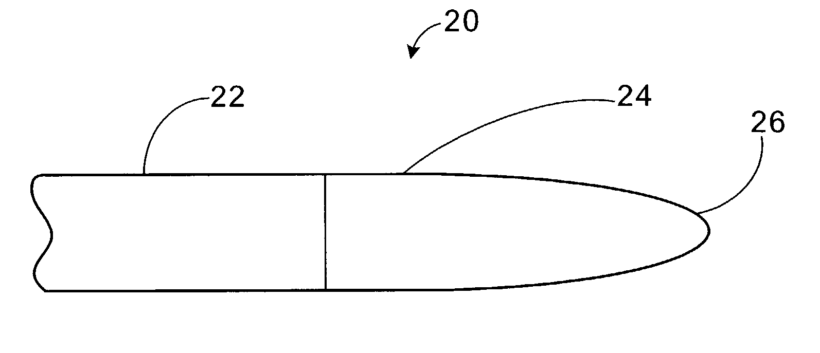
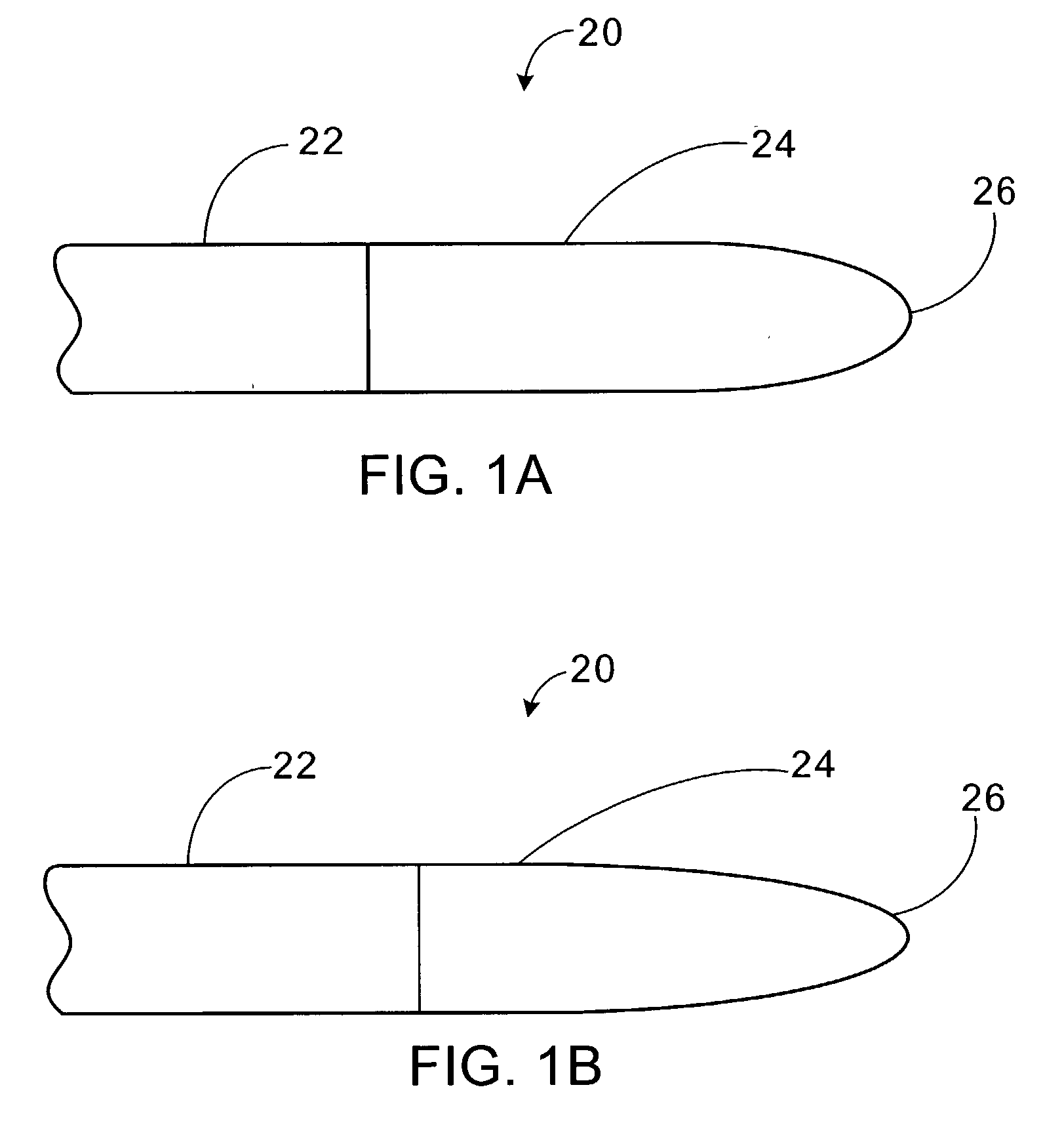
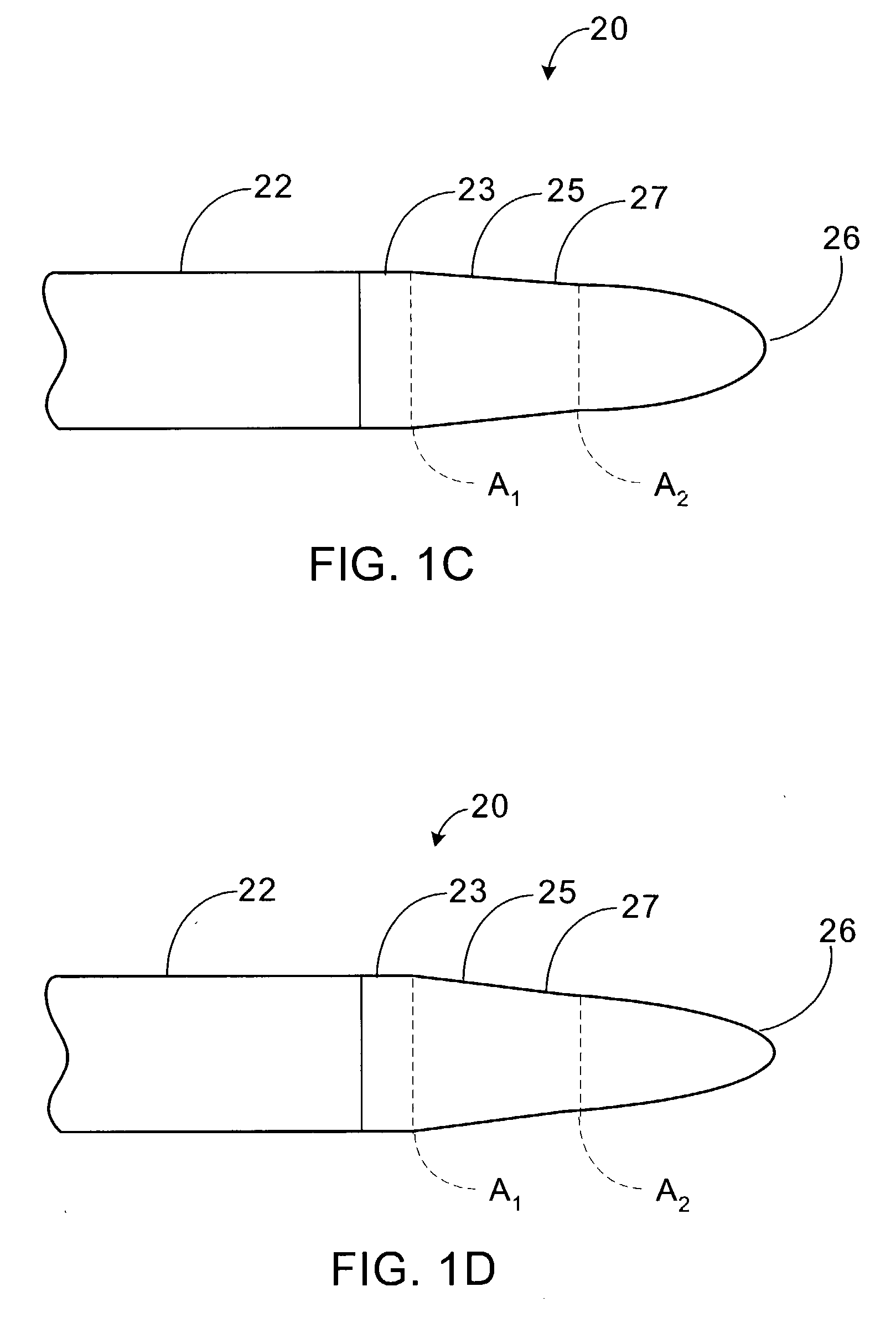
Beam altering fiber lens device and method of manufacture
a fiber lens and beam-altering technology, applied in the direction of optical fibre with graded refractive index core/cladding, optical waveguide light guide, instruments, etc., can solve the problems of index gradient being produced by ion exchange process that is both time-consuming and expensive, and refraction at these surfaces
- Summary
- Abstract
- Description
- Claims
- Application Information
AI Technical Summary
Benefits of technology
Problems solved by technology
Method used
Image

Examples
Embodiment Construction
[0076] An example of an in-line beam altering multi-lens apparatus and optical assembly in accordance with the above-mentioned embodiments of the present invention will now be described.
[0077] An exemplary in-line multi-lens apparatus 80, including a biconic lens 26, is shown schematically in FIG. 7 with reference to the variables described below. The exemplary multi-lens apparatus includes a source 82 of an optical signal, in this case a laser diode capable of emitting a signal at an operating wavelength `wav`; Mode-field-diameter (MFD) in the x-direction (vertical direction) of wx0 (.mu.m), and MFD in the y-direction of wy0 (.mu.m). The beam from the source 82 propagates through a medium (most commonly air) of index (n1) for a distance (z) before falling on a biconic lens 26 with radii of curvature of (RLx) (.mu.m) in the x-direction and (Rly) (.mu.m) in the y-direction that is formed on a spacer rod 36 having a radially constant refractive index profile and a length (Lc) and inde...
PUM
 Abstract
Description
Claims
Application Information