Brushless dc drive

US20030173850A1Inactive Publication Date: 2003-09-18ROBERT BOSCH GMBH

Image

  • Brushless dc drive
  • Brushless dc drive
  • Brushless dc drive

Examples


Embodiment Construction

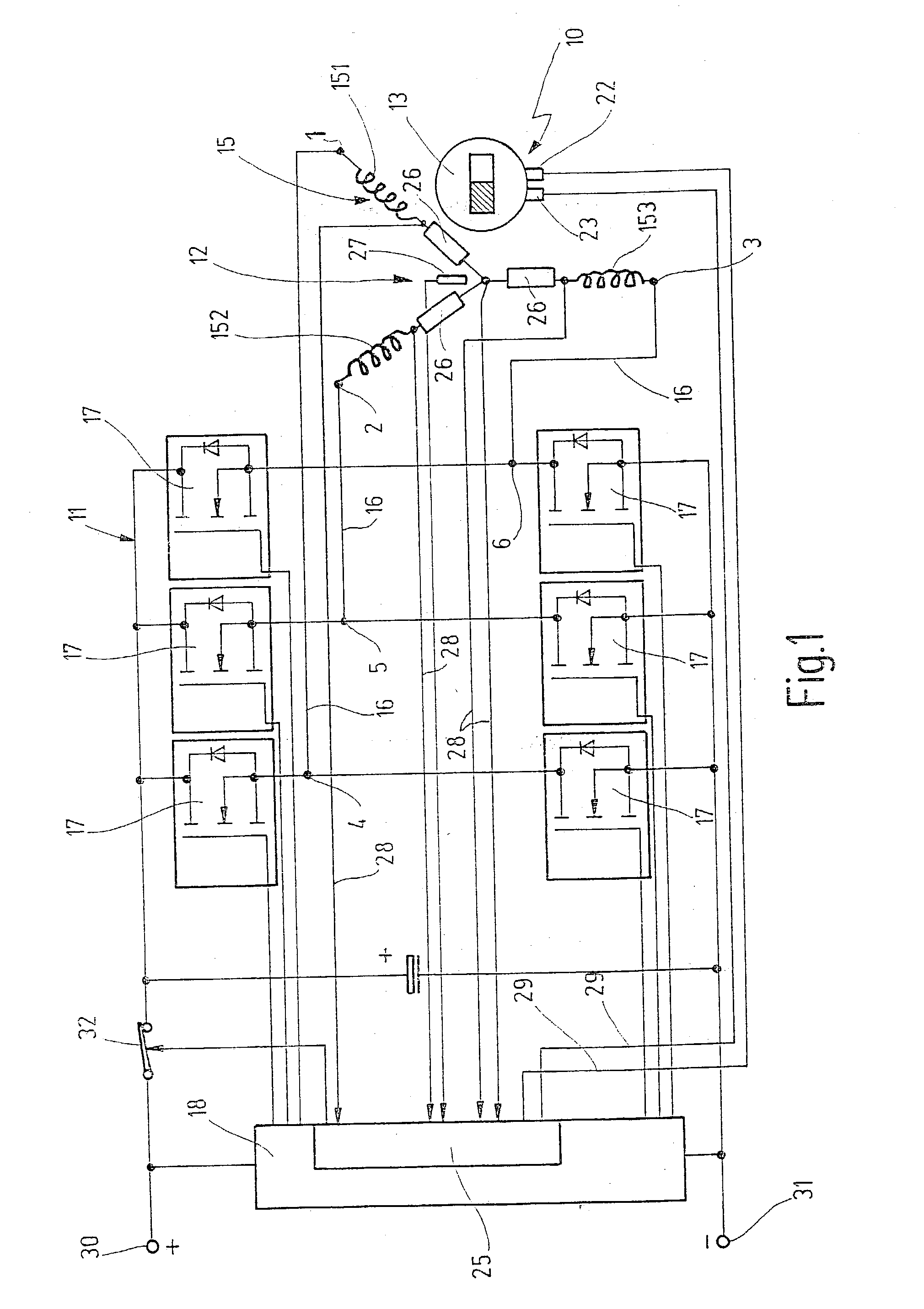
[0014] The brushless direct-current drive shown in the circuit diagram in FIG. 1 has a synchronous motor 10, which is operated by means of a switch unit 11 for electronic commutation in a DC voltage network, which is characterized in FIG. 1 with "+" and "-" and is connected to connecting terminals 30, 31 of the direct-current drive.

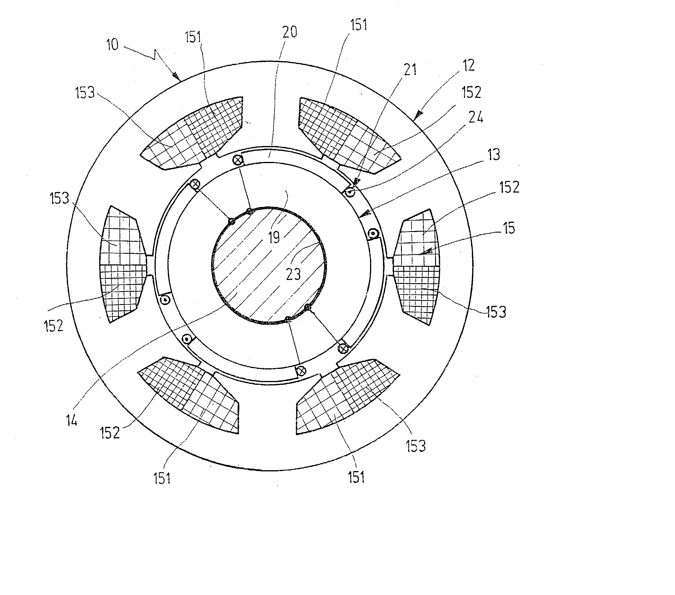
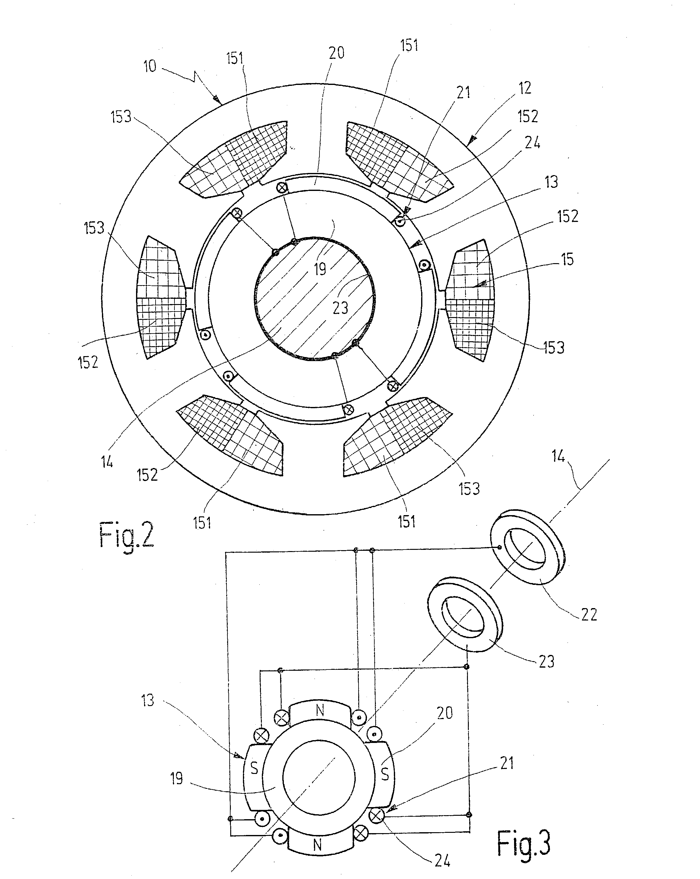
[0015] In a known fashion, the synchronous motor 10 has a stator 12 and a rotor 13, which is supported on a rotor shaft 14 (FIG. 2), which is in turn supported in rotary fashion in a housing. The stator 12 supports an armature or stator winding 15, which is embodied as three-phase in the exemplary embodiment and whose winding phases 151-153 are wired in a star pattern. The winding connections 1, 2, and 3 of the stator winding 15 are each connected to the switch unit 11 via a connecting line 16.

[0016] The switch unit 11, which is embodied as a B6 inverter, has six semiconductor power switches 15 in a bridge circuit, which in the exemplary embodiment are em...


PUM


Abstract

In a brushless direct-current drive with a synchronous motor (10), which has a stator (12) that supports a multi-phase stator winding (15) and a rotor (13) equipped with permanent magnet poles (20), and with a switch unit (11), which precedes the stator winding (15), for commutating the stator winding (15), in order to produce a fail-silent behavior, a field excitation winding (21) is disposed in the rotor (13), which winding can be supplied with current in the event of a malfunction so that it generates a magnetic flux oriented in the opposite direction from the magnetic flux of the permanent magnet poles (20) (FIG. 2).

Description

PRIOR ART[0001] The invention is based on a brushless direct-current drive according to the preamble to claim 1.[0002] In motor vehicles, permanent magnet-excited, brushless direct-current drives are used for a variety of purposes, including for electric steering boosters. These direct-current drives have a synchronous motor with a stator or armature winding and a permanent magnet-excited rotor. The armature winding is connected to the DC voltage network by means of an inverter in a bridge circuit with semiconductor power switches. The inverter that executes the commutation of the stator winding is triggered by an electronic control unit.[0003] DE 37 09 168 A1 describes a synchronous motor operated in a DC voltage network in which three semiconductor power switches triggered by a control unit are disposed in the winding strands of the stator winding, which is wired in a star pattern. If malfunctions occur in the stator winding and / or in the power switches, then the direct-current dr...

Claims


Application Information

Patent Timeline
18 Sep 2003
Publication
US20030173850A1
IPC
H02K21/04; H02K29/00; H02P6/34; H02P29/02
CPC
H02K21/042; H02P29/02; H02P6/001; H02P6/34; H02K21/04
Inventors
BEYER, STEFAN; WITZIG, HARALD