
Reactor for exothermic or endothermic heterogeneous reactions

a technology of exothermic or endothermic heterogeneous reactions and heterogeneous reactions, which is applied in the direction of physical/chemical process catalysts, lighting and heating apparatus, laminated elements, etc., can solve the problems of low outflow speed, high water flow rate, and reduced heat exchange efficiency

Inactive Publication Date: 2003-09-18
CASALE SA
View PDF12 Cites 15 Cited by
  • Summary
  • Abstract
  • Description
  • Claims
  • Application Information

AI Technical Summary

Benefits of technology

[0027] Thanks to the present invention it is advantageously possible to obtain--in an easy and effective way--an isothermal reactor at high heat exchange degree that allows an optimum control of the temperature, to all advantage of the conversion yield and of the energy consumption.
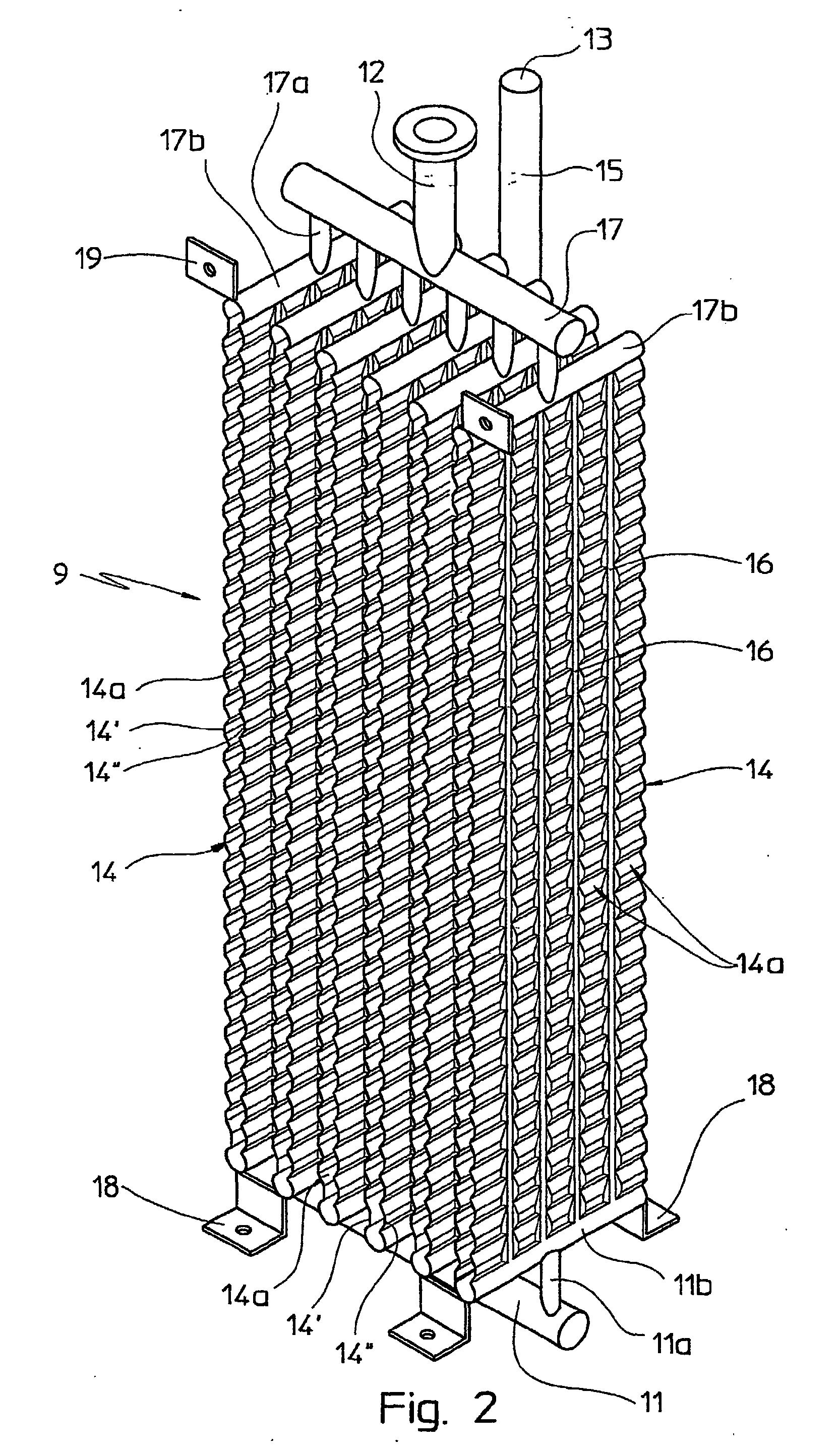
[0031] This means that each single duct of the plate exchanger according to the present invention is in contact with the same portion of reactants thereby advantageously following all the variations of heat developed or absorbed by the reaction; therefore it is possible to obtain a predetermined temperature profile for the reaction in run.
[0033] The higher heat exchange efficiency inside the reactor according to the invention allows recovering or supplying heat with smaller temperature differences between the reactant fluid and the heating or cooling fluid. This advantage implies a smaller gradient of temperature inside the catalytic layer between two adjacent plates, hence achieving a greater uniformity of temperature inside the catalytic layer and therefore an increase of the conversion yield with respect to the reactors according to the prior art. Or, the conversion yield being the same, the increase of the heat exchange efficiency allows decreasing the required volume of catalyst with the ensuing savings in terms of space and investment costs.
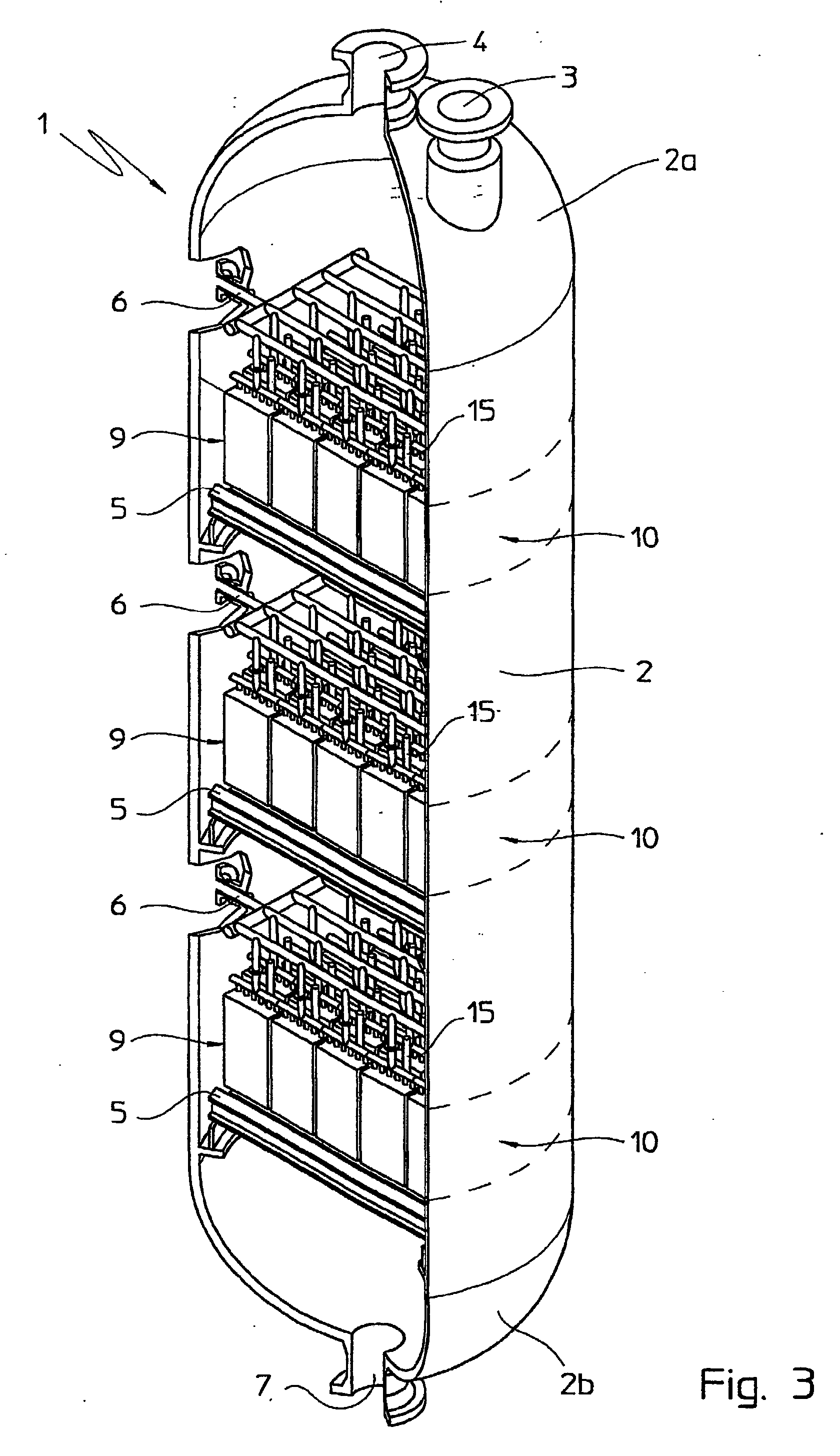
[0034] A further advantage arising with the present invention consists in that when a plurality of ducts is arranged inside a catalytic layer, such ducts may all be fed from a same source of supply because--all of them undergoing the same thermal load--there are no problems of control of the supply and removal of the cooling / heating fluid.
[0035] Further on, thanks to the structural simplicity of the heat exchangers it is possible to carry out their maintenance in a particularly easy and cost-effective way.

Problems solved by technology

Further on, the substantial detected reduction of heat exchange efficiency is also due to the fact that the ducts of the aforesaid arrangement in contact with the gaseous reactants at low temperature are subjected to a low thermal load, what implies a low degree of vaporisation for the water with ensuing low outflow speed and hence high water flow rates, in terms of mass.
On the contrary, the helicoidal tubes in contact with the high temperature gaseous reactants are subjected to a high thermal load, what implies a high degree of vaporisation for the water with ensuing high outflow speed and hence low water flow rates, in terms of mass.
A further disadvantage of the reactor according to the prior art is its high structural and manufacturing complexity resulting from the helicoidal design of the tube bundle that requires for sure high investment and maintenance costs.
It shall be noted that in some cases such structural complexity may even make it impossible to carry out its maintenance.
Just because of these disadvantages, the isothermal reactors for carrying out exothermic or endothermic heterogeneous syntheses of the above-mentioned type have found to date little practical application, notwithstanding the increasingly felt need in the field of high capacity reactors.
Such drawbacks do even get worse in case the isothermal reactor in use is not of the above mentioned helicoidal tube bundle type but of the vertical tube bundle type.

Method used


Image

  • Reactor for exothermic or endothermic heterogeneous reactions
  • Reactor for exothermic or endothermic heterogeneous reactions
  • Reactor for exothermic or endothermic heterogeneous reactions

Examples


Embodiment Construction

[0043] By making reference to the aforementioned drawings, the apparatus according to the present invention is described as follows.

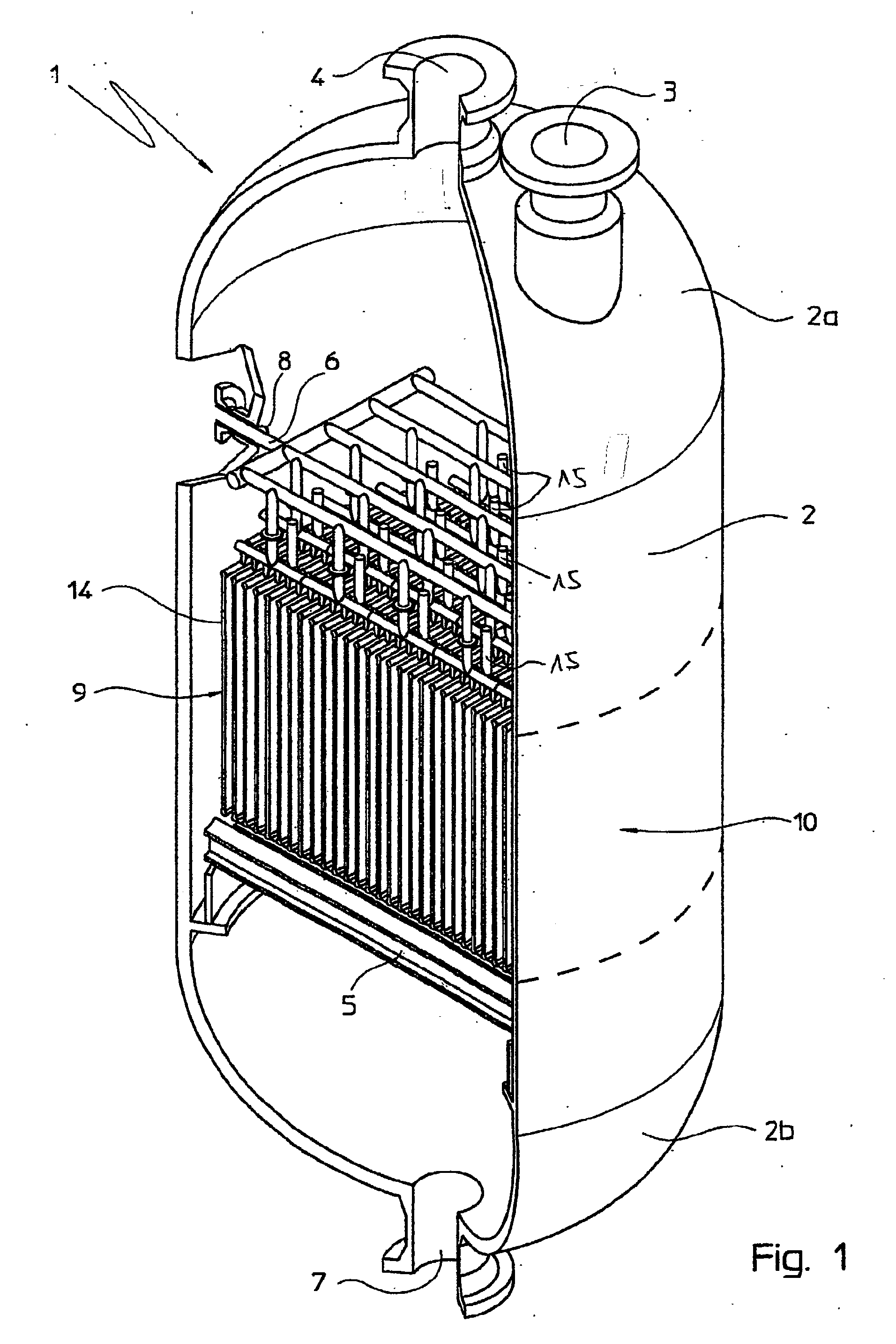
[0044] With reference to FIG. 1 an isothermal reactor 1 with an outer shell 2 is shown, which is for carrying out exothermic or endothermic heterogeneous reactions.

[0045] Such shell 2 has a cylindrical structure closed at its ends by respective bottoms, an upper bottom 2a and a lower bottom 2b, in which the aperture 3 and 4 and the aperture 7 are provided, respectively.

[0046] The circular aperture 4 for the inlet of the gaseous products to be made react is arranged onto the top of the upper bottom 2a of the shell 2. Such aperture 4 directly faces the inside of the shell.

[0047] The aperture 3 is arranged on the upper bottom 2a of the shell 2 beside the aperture 4 whereby it faces the inside of the shell, too.

[0048] At the end of the bottom 2b of the shell 2 the aperture 7 is provided, which directly faces the inside of the shell 2.

[0049] Such apertures a...


PUM

PropertyMeasurementUnit
diameteraaaaaaaaaa
dimensionaaaaaaaaaa
cylindrical shapeaaaaaaaaaa

Abstract

A reactor (1) for carrying out exothermic or endothermic heterogeneous reactions comprising an outer shell (2) of substantially cylindrical shape and at least a heat exchanger (9) embedded in a catalytic layer (10) supported in said shell (2), is characterised in that the heat exchanger (9) is a plate (14) heat exchanger.

Description

[0001] The present invention relates to an isothermal reactor for carrying out exothermic or endothermic heterogeneous reactions, of the type comprising:[0002] an outer shell of substantially cylindrical shape;[0003] at least a heat exchanger embedded in a catalytic layer supported into such shell.[0004] In the following description and attached claims, the expression "isothermal reactor" is meant to indicate a reactor for chemical reactions wherein the temperature inside the one or more catalytic layers where the reaction takes place, is controlled by essentially removing or supplying heat. Such reaction may be of both of exothermic or endothermic type. On the contrary, the expression "adiabatic reactor" is meant to indicate a reactor for chemical reactions wherein inside the one or more catalytic layers where the reaction takes place, there is no heat exchange with the outer environment.[0005] As known, in the field of exothermic or endothermic heterogeneous synthesis, the need is...

Claims


Application Information

Patent Timeline
Patent Type & Authority Applications(United States)
IPC IPC(8): B01J8/02B01J8/04B01J19/24F28D9/00F28F9/26
CPCB01J8/0214F28F9/26B01J8/0285B01J8/0453B01J8/0496B01J19/249B01J2208/0015B01J2208/022B01J2208/025B01J2219/00024B01J2219/2453B01J2219/2455B01J2219/2458B01J2219/2462B01J2219/2481B01J2219/2485B01J2219/2493B01J2219/2495F28D9/0006F28D9/0025F28D9/0093F28F9/0275B01J8/025
Inventor FILIPPI, ERMANNORIZZI, ENRICOTAROZZO, MIRCO
Owner CASALE SA
Learn More