Method for preparing carbon nano-fine particle, apparatus for preparing the same and mono-layer carbon nanotube

a carbon nanotube and monolayer technology, applied in the field of carbon nanofine particle preparation, apparatus for preparing the same and monolayer carbon nanotube, can solve the problems of high cost of co.sub.2 laser, inconvenient continuous mass production, and high cost of apparatus

Inactive Publication Date: 2003-10-09
HIROFUMI TAKIKAWA +2
View PDF1 Cites 15 Cited by
  • Summary
  • Abstract
  • Description
  • Claims
  • Application Information

AI Technical Summary

Benefits of technology

[0015] 1) A vacuum container, evacuating apparatus, laser-introducing vacuum window and CO.sub.2 laser are necessary. Apparatus cost is relatively high. In particular, a CO.sub.2 laser is high expensive.
[0019] A principal object of the present invention is to provide a method of producing carbon nano-fine particle (including a mass production) containing about 20% and above of carbon nanohorn fine particles easily and at low cost in which a process container is not always necessary and a carbon material is evaporated by the use of arc jet generated in air, and an apparatus for preparing the same. Further object of the present invention is to provide a novel nanocarbon substance.

Problems solved by technology

Apparatus cost is relatively high.
In particular, a CO.sub.2 laser is high expensive.
2) Since the production process is carried out in an Ar gas-charged hermetically sealed container, it is not suitable for continuous mass production.
4) When the window for introducing the laser is contaminated with carbon soot, cleaning the window must be repeated frequently because graphite material is not irradiated with a laser having the desired power.
Accordingly, the equation of conditions is difficult and such a conventional method is not suitable for continuous mass production.

Method used


Image

  • Method for preparing carbon nano-fine particle, apparatus for preparing the same and mono-layer carbon nanotube
  • Method for preparing carbon nano-fine particle, apparatus for preparing the same and mono-layer carbon nanotube
  • Method for preparing carbon nano-fine particle, apparatus for preparing the same and mono-layer carbon nanotube

Examples


Embodiment Construction

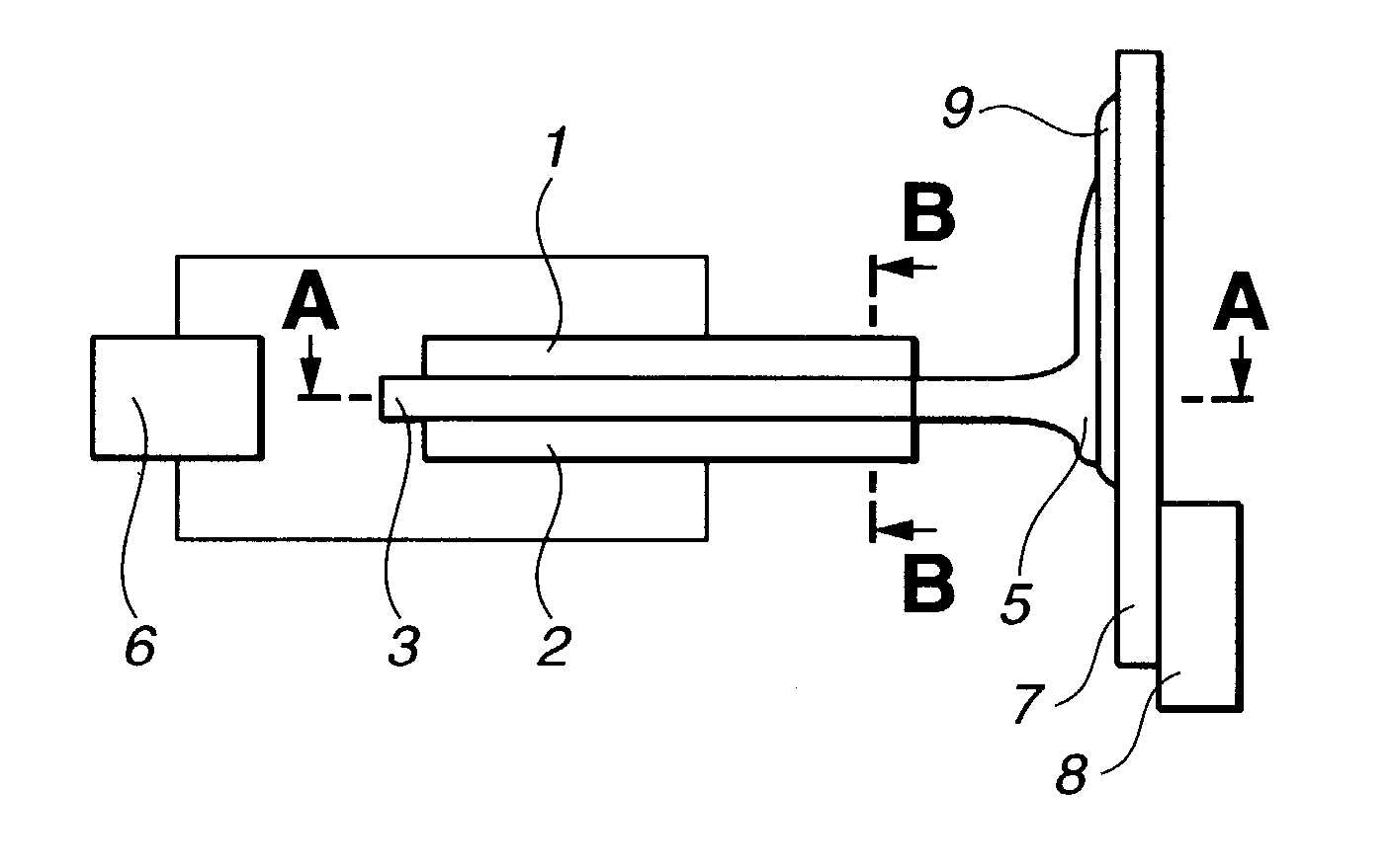
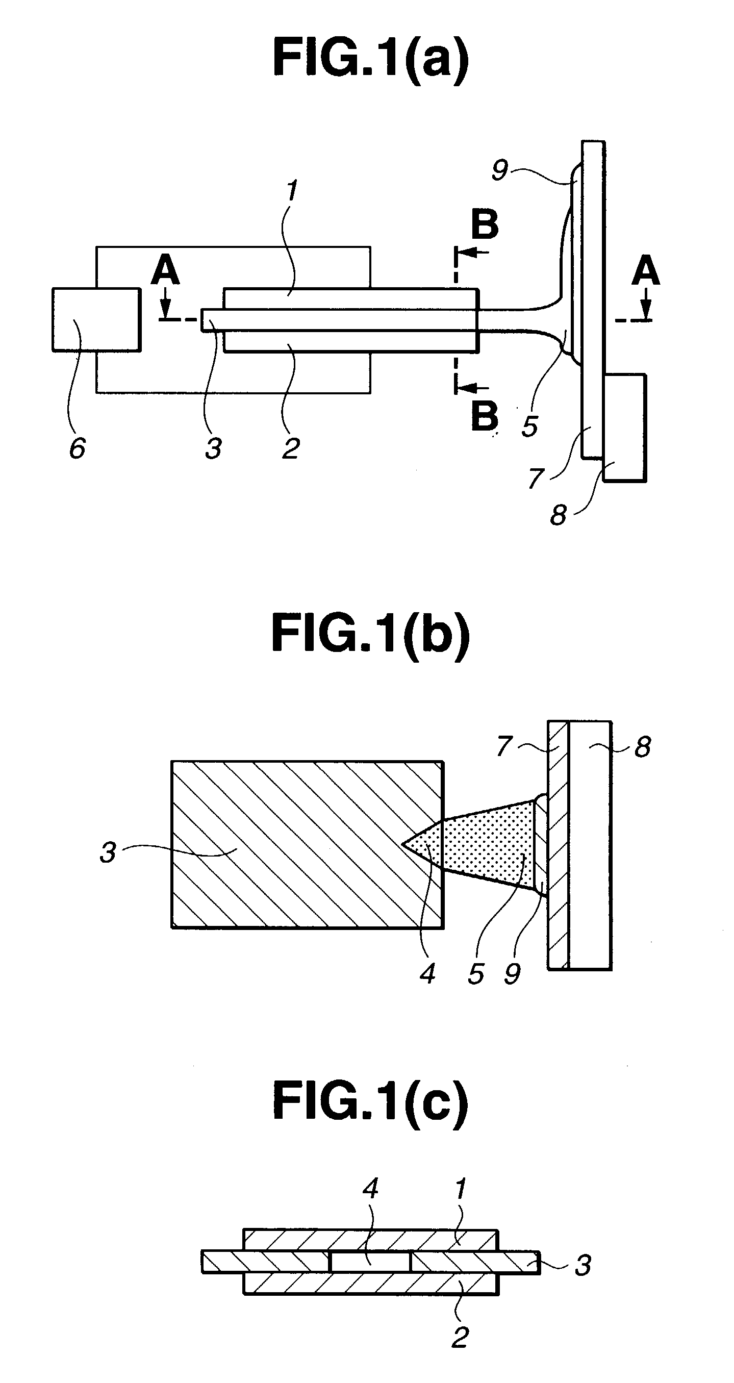
is describe below with reference to FIG. 1. FIG. 1(a) is a schematic illustration of an apparatus used in example 1 for preparing a carbon nano-fine particle. FIG. 1(b) is a cross section taken along a plane A-A of FIG. 1(a). FIG. 1(c) is a cross section taken along a plane B-B of FIG. 1(a).

[0058] As shown in FIG. 1, the apparatus of the present invention comprises a cathode 1 of graphite as a first electrode, an anode 2 made of carbon material, such as graphite, active carbon, amorphous carbon, resin, etc., placed opposite the cathode 2, an insulating plate 3 placed between the cathode 1 and anode 2, the notch 4 formed in the insulating plate so as to expose the cathode 1 to the anode 2 oppositely, a welding electric source 6 for applying voltage between the cathode 1 and anode 2 to generate an arc jet (arc) 5 by arc discharge, thereby evaporating the carbon material of the anode 2 to generate soot containing carbon nanomaterial, a substrate (base plate) 7 of stainless steel etc. p...


PUM

PropertyMeasurementUnit
lengthaaaaaaaaaa
lengthaaaaaaaaaa
lengthaaaaaaaaaa

Abstract

A graphite cathode and a graphite anode are placed opposite each other through an insulating plate having a notch. A voltage is applied between both of the electrodes to generate arc discharge at the notch of the insulating plate. A given area of the graphite anode is evaporated from an electrode point of the arc discharge, and simultaneously an arc jet is generated from the notch. Thereby, a carbon nanoparticle comprising soot of carbon nanomaterial containing carbon nanohorn is generated. The soot is deposited on a recovering plate for recovery.

Description

[0001] Not Applicable[0002] Not Applicable[0003] 1. Field of the Invention[0004] The present invention relates to a method for effectively preparing at low cost a nanoscale size (10.sup.-6-10.sup.-9) particle comprising a carbon nanohorn or extremely short monolayer carbon nanotube containing carbon, such as, graphite, activated carbon, amorphous carbon, resin etc., as main components and an apparatus for preparing the same. The present invention is particularly applicable to the production of a mixture for a secondary battery electrode or fuel battery electrode. The present invention also relates to a novel nanocarbon substance.[0005] The term "carbon nanohorn" used herein is a carbon nanoparticle having a shape of a graphite sheet that is rounded conically with a closed peak (see: Unexamined Japanese Patent Publication (Kokai) No. 2001-64004).[0006] The term "extremely short mono-layer carbon nanotube" used herein is defined as a mono(single)-layer carbon nanotube having a length ...

Claims


Application Information

Patent Timeline
Patent Type & Authority Applications(United States)
IPC IPC(8): B01J19/08C01B31/02
CPCB01J19/088B01J2219/00155B01J2219/0809B01J2219/0822B01J2219/0835B01J2219/0839C01B2202/36B01J2219/0886B01J2219/0892B82Y30/00B82Y40/00C01B31/0233C01B2202/34B01J2219/0871C01B32/162C01B32/05B82B3/00
Inventor TAKIKAWA, HIROFUMIIKEDA, MITSUKUNIITOH, SHIGEOTAHARA, TOMONORI
Owner HIROFUMI TAKIKAWA
Why Eureka
Try Eureka