Power processor

a power processor and processor technology, applied in the field of electric power supplies, can solve the problems of severe requirements for uninterrupted power, computer and other sophisticated electronic devices subject to malfunction, and the inherently subject of failure of the apparatus,

Inactive Publication Date: 2003-10-23
HATTON THOMAS E +1
View PDF19 Cites 58 Cited by
  • Summary
  • Abstract
  • Description
  • Claims
  • Application Information

AI Technical Summary

Benefits of technology

[0013] It is another object of the invention to provide a power supply which can provide a wide range of voltages efficiently with an easily maintained modular articulation which provides scalability over a wide range and enhanced reliability through increased redundancy.
[0014] It is a further object of the invention to provide an uninterruptible power supply architecture as a power processor which is compatible with the provision of protection from environmental conditions such as EMI interference and emissions.
[0015] It is yet another object of the invention to support reliable operation of commercial off-the-shelf electronic equipment as well as specially built electronic equipment in severe environments.
[0016] In order to accomplish these and other objects of the invention, a power processor having the function of an uninterruptible power supply is provided including a plurality of relatively low power but scalable, high efficiency DC / DC converters in each of a plurality of converter modules to provide N+1 redundancy, each having one or more capacitors for power storage at a relatively high voltage preferably at least twice that of the output of the DC / DC converters in order to increase power storage. Battery back-up power can be provided to increase the time power output is maintained without input power, if needed or desired. Active power factor correction and electromagnetic interference filtering is preferably provided in common for all converter modules which, due to the high efficiency and low heat dissipation of the DC / DC converters, can be packaged in a dense, compact form in a housing adaptable for standard rack mounting. An output bus common to some or all of the converter modules provides graceful degradation and smooth shifting of load between converter modules and between phases of input power without need for additional control when one or more converter modules fail. DC Power is provided to processors and other types of electrical equipment and the loss of efficiency required in re-conversion to AC power is thus avoided; allowing the dense and compact packaging and avoidance of more complex and energy-consuming forms of heat removal.

Problems solved by technology

Such apparatus, of course, is inherently subject to failure while the use of computers and other sophisticated electronic apparatus which are subject to malfunction or damage from momentary interruptions or fluctuation of power is increasing.
However, even static installations such as computers in offices present severe requirements for uninterrupted power and the use of back-up systems such as diesel powered generators and so-called uninterruptible power supplies are being installed with increasing frequency to answer this need.
However, while known uninterruptible power supplies (UPS) are highly reliable for providing continuous power, most units in use for protection of computers are of limited capacity and provide only a few minutes of power to allow a back-up generator to be brought on line or the system to be shut down, if necessary, without loss or corruption of data.
Further, UPS devices are generally heavy due to the inclusion of rechargeable batteries and are of relatively low efficiency, generally in the range of 70% to 80%, thus dissipating significant quantities of heat, particularly due to the conversion process of converting DC, required for battery back-up, back to AC.
That is, the low efficiency of UPS devices is principally due to the use of inverters to supply alternating current power similar to commercially available power provided by public utilities.
However, they present further and severe problems in mobile installations where high density UPS installation is not generally practical due to a combination of size, weight and heat dissipation.
Further, conventional UPS devices cannot be ganged together with a common output bus to provide additional power supply capacity and / or redundancy without complex synchronization arrangements or output switching which, in any event, cannot be provided instantaneously.
Systems with larger power requirements generally utilize other forms of redundancy that are usually much less capable of avoiding at least momentary interruptions and fluctuations of power.
However, even in such a case, the switching may require several tens of milliseconds (e.g. seventy milliseconds for mechanical switches generally used at present) which is sufficiently long to cause malfunction and / or damage to many commercially available (e.g. commercial off-the-shelf or COTS) processors and other devices.
Processors running UNIX or LINUX, as is increasingly common in larger systems, have been found susceptible to malfunction or damage by momentary interruptions of power.
Additionally, the power requirements for mobile systems is often highly variable and may be very different in different installations.
While installation-specific power supplies could be designed, it is often not practical to do so since original design work is costly and equipment made in small numbers is relatively more costly to manufacture and maintain.
Further, known UPS device designs are generally scalable over only a relatively narrow range of power capacities and then often only at the expense of reduced efficiency.
In summary, the reliability of a wide variety of electronic equipment is often limited by the reliability of the power supply which can be provided and which is often compromised by the environment in which the equipment and power supply is to operate.
Known, commercially available UPS devices are of low electrical and spatial efficiency and produce substantial amounts of heat which must be dissipated, often in environments in which heat dissipation is difficult.
For example, air conditioning, fluid cooling or the like requires significant amounts of additional power and effectively further reduces efficiency of the overall installation and will often be required due to space limitations in environments where power availability is at a premium.
Reduction of electromagnetic interference effects as well as limitations on available space cause high density of power conversion equipment while achievement of high density is generally limited or seriously compromised by heat dissipation requirements.

Method used


Image

  • Power processor
  • Power processor
  • Power processor

Examples


Embodiment Construction

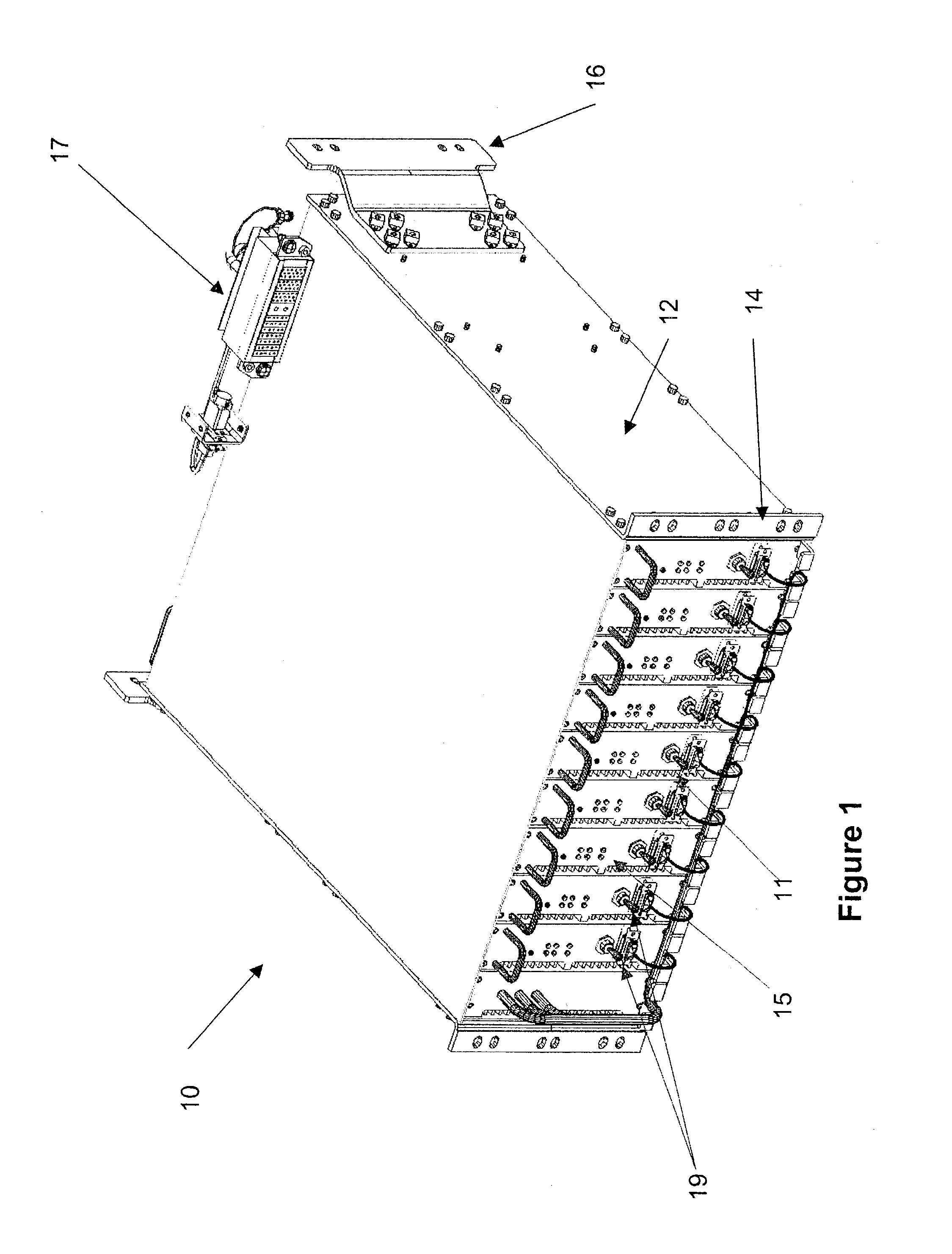
[0022] Referring now to the drawings, and more particularly to FIG. 1, there is shown, in perspective view, a preferred physical form of the power processor 10 in accordance with the invention. This embodiment of the invention is intended to have a nominal power supply capacity of 6.0 KiloWatts (kW) and a maximum power supply capacity of 9.0 kW at a DC output voltage of one hundred fifty volts. Preferably, in view of the projected applications of the invention in mobile machines, the power processor is packaged in hardware suitable for standard rack mounting which advantageously provides for convenient and standardized cooling arrangements as will be discussed in greater detail below. However, neither the packaging nor the details of the cooling arrangement is critical to the successful practice of the invention. Electrical connections such as output connections 17, module input power via 19 or connections on the rear of the housing 12 can be made at either the front or back side of...


PUM


Abstract

An uninterruptible power supply (UPS) provides DC output power and uses a plurality of relatively low power DC / DC converters which are of much higher efficiency and lower heat dissipation than inverters normally used in UPS devices to provide AC output power. Power is stored at high voltage in capacitors to provide output power when input power may be interrupted. Since the power dissipation is reduced and use of batteries can be avoided where redundant input power sources are available, the UPS made be made very compact and of light weight as is particularly suited to mobile machinery such as aircraft, water-borne vehicles and the like.

Description

[0001] This application claims benefit of priority of U.S. Provisional Patent Application No. 60 / 369,761 filed Apr. 5, 2002; which application is hereby fully incorporated by reference.[0002] 1. Field of the Invention[0003] The present invention generally relates to electrical power supplies and, more particularly, to compact uninterruptible power supplies particularly useful in complex mobile systems such as aircraft and water-borne vessels.[0004] 2. Description of the Prior Art[0005] The generation of electrical power generally requires the conversion of energy which is stored either mechanically or chemically, as in fossil or nuclear fuels or storage batteries and therefore generally requires apparatus of substantial size in order to generate significant amounts of electrical power. Such apparatus, of course, is inherently subject to failure while the use of computers and other sophisticated electronic apparatus which are subject to malfunction or damage from momentary interrupti...

Claims


Application Information

Patent Timeline
Patent Type & Authority Applications(United States)
IPC IPC(8): H02J9/06
CPCH02J9/062H02J2310/40Y04S20/20Y02B70/30
Inventor HATTON, THOMAS E.BIERLY, MEADE G.
Owner HATTON THOMAS E
Why Eureka
Try Eureka