Sensor alignment method for 3D measurment systems

a technology of measuring system and sensor, applied in the direction of instruments, image data processing, material analysis, etc., can solve the problem of not properly focused viewing system

Inactive Publication Date: 2003-11-13
GENERAL ELECTRIC CO
View PDF6 Cites 14 Cited by
  • Summary
  • Abstract
  • Description
  • Claims
  • Application Information

AI Technical Summary

Benefits of technology

0006] Finally, the temperature and humidity of the test facility is controlled to provide an optimal tes...

Problems solved by technology

If the shape and position of the lines projected onto a section changes along the l...

Method used


Image

  • Sensor alignment method for 3D measurment systems
  • Sensor alignment method for 3D measurment systems
  • Sensor alignment method for 3D measurment systems

Examples


Embodiment Construction

[0014] The following detailed description illustrates the invention by way of example and not by way of limitation. The description clearly enables one skilled in the art to make and use the invention, describes several embodiments, adaptations, variations, alternatives, and uses of the invention, including what is presently believed to be the best mode of carrying out the invention.

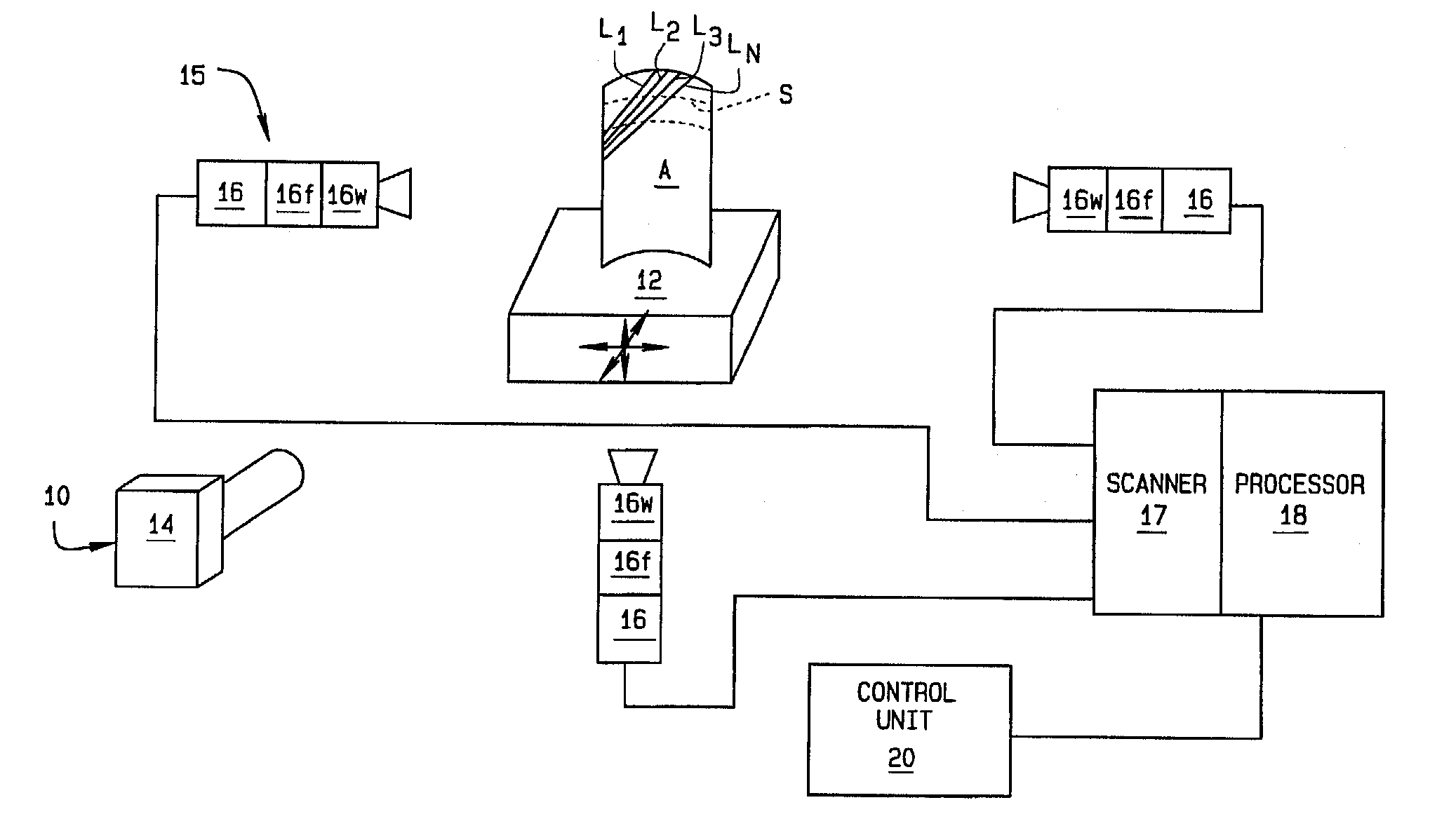
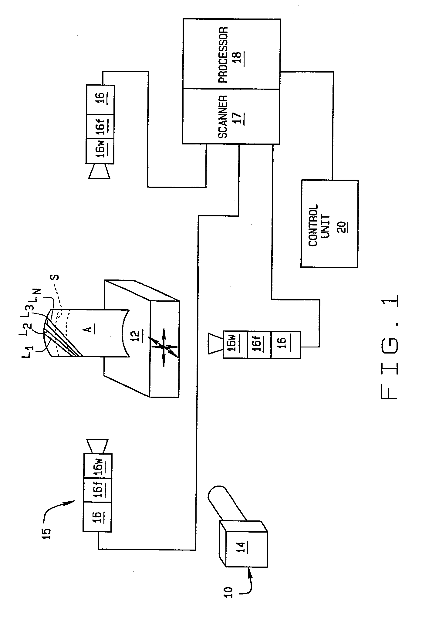
[0015] Referring to FIG. 1, the test setup for a structured light system 10 used for light gauge testing of an airfoil A or similar part with a complex surface contour first includes a support or fixture 12 on which the airfoil is mounted. The fixture may be a movable fixture having six degrees of freedom so the part can be moved to any desired orientation. To test the part for acceptability, a laser light is projected onto the object from a laser light projector 14 and light reflections from the object are obtained using an imaging system 15. System 15 includes one or more cameras 16. These include wind...


PUM


Abstract

A method of set up and alignment of a structured light system for light gauge testing of an object (A). An initial alignment is made of the system with a test specimen mounted in a fixture. Light stripes (L1-Ln) generated by the structured light system are projected onto the part and images of the reflections are captured by cameras and evaluated to determine the characteristics of each stripe over a section of the specimen. The characteristics checked include the number of pixels extending across the width of a line, centeredness of the line, and the distribution of light intensity. If the former two features are not within predetermined limits, or if intensity distribution is not Gaussian, the test setup is adjusted and the process repeated. An imaging system used in the test is also checked to verify the quality of the images captured and processed. If necessary, viewing windows, polarizers, and other electrical components are evaluated to insure the imaging system is properly focused. The temperature and humidity of the test facility are also controlled to provide an optimal testing environment in which performance of the components is not effected by extremes of either.

Description

BACKGROUND OF INVENTION[0001] This invention relates to the measurement of physical characteristics of three dimensional (3D) objects such as turbine blades used in aircraft engines and the like, and more particularly, to a method for checking the alignment of a structured light 3D measurement system employed in such testing using line video data and interferometry tools.[0002] In testing of objects such as turbine blades which have a complex outer surface or contour, it is advantageous to employ a light gauging testing methodology rather than using conventional hard gauging techniques. This involves the use of a structured light system such as the 4DI light system available from Intelligent Automation. To obtain the most accurate test data for evaluating a part to determine its acceptability, the structured light system employed must be properly setup and aligned. Minor variations in the width of lines of light projected by the structured light system onto the object, for example, ...

Claims


Application Information

Patent Timeline
IPC IPC(8): G01B11/00G01B11/25G01N21/95
CPCG01B11/25G06T7/521G01N21/9515G01B11/2504
Inventor HARDY, KEVIN GEORGE
Owner GENERAL ELECTRIC CO
Why Eureka
Try Eureka