Fuel injection control system for internal combustion engine

a control system and internal combustion engine technology, applied in the direction of electric control, machines/engines, mechanical equipment, etc., can solve the problems of white smoke or an unburned fraction of fuel, increased flow resistance at the particulate filter, and insufficient oxidization ability of the catalyst,

Inactive Publication Date: 2003-12-04
DENSO CORP
View PDF7 Cites 30 Cited by
  • Summary
  • Abstract
  • Description
  • Claims
  • Application Information

AI Technical Summary

Problems solved by technology

Since the particulate filter is made of a porous material, flow resistance at the particulate filter may increase if an excessive quantity of the particulate matters is collected.
Therefore, there is a possibility that the oxidization ability of the catalyst may become insufficient even if a theoretical quantity of the fuel corresponding to the heating value required for eliminating the collected particulate matters is injected in the post-injection.
As a result, white smoke, or an unburned fraction of the fuel, may be generated.

Method used


Image

  • Fuel injection control system for internal combustion engine
  • Fuel injection control system for internal combustion engine
  • Fuel injection control system for internal combustion engine

Examples


Embodiment Construction

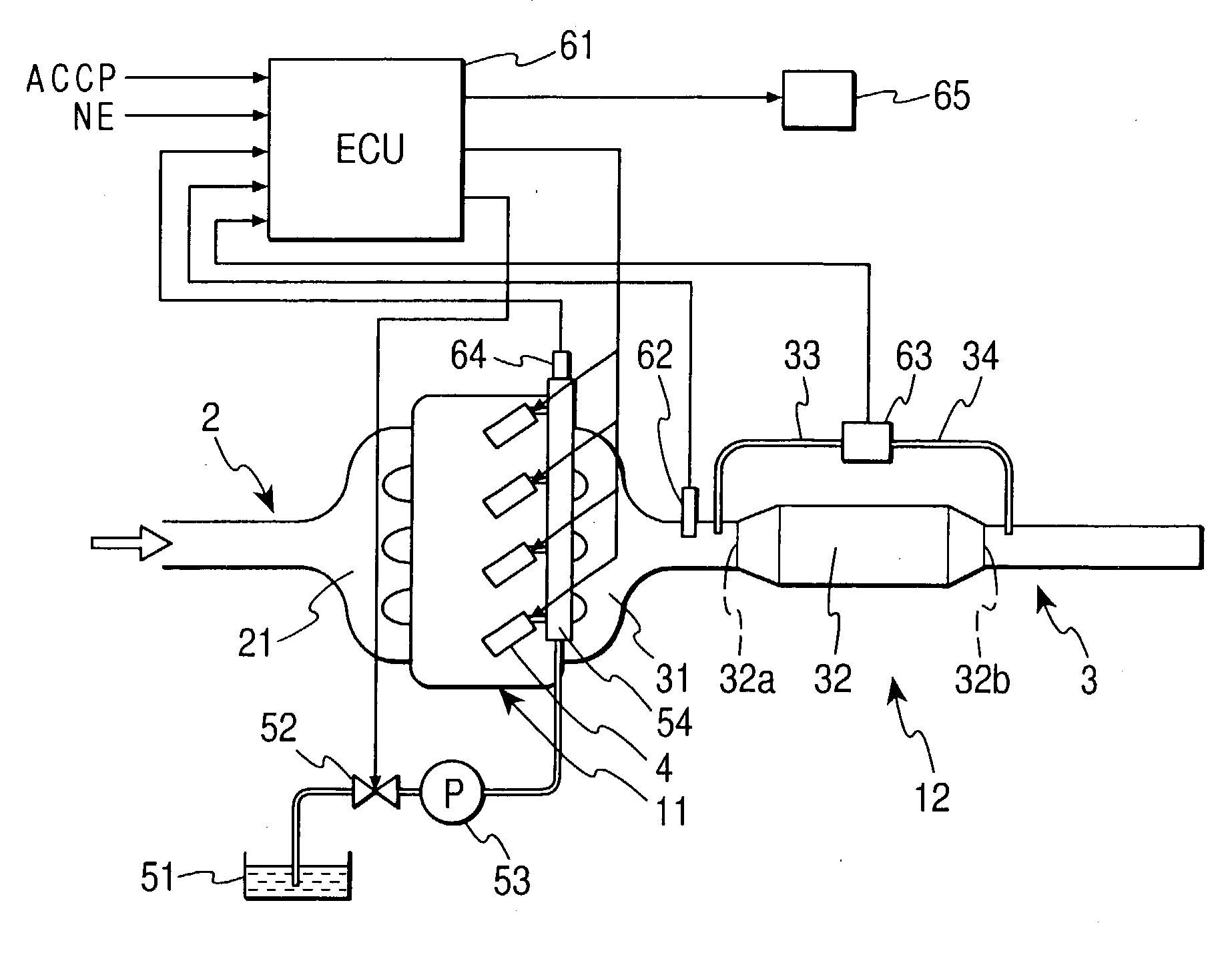
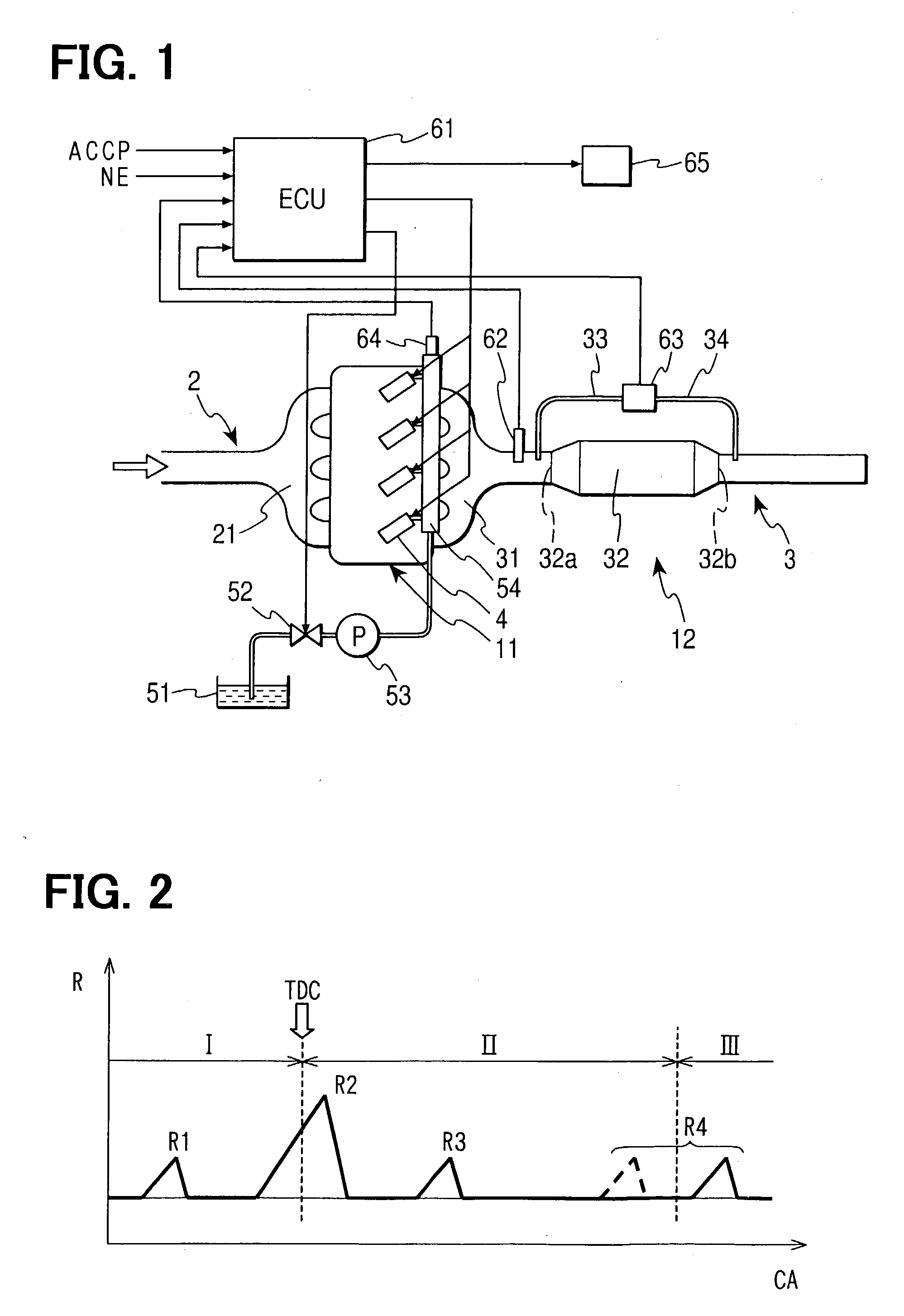
[0020] Referring to FIG. 1, a diesel engine having a fuel injection control system according to an embodiment is illustrated. The diesel engine has a four-cylinder type engine main body 11 and an after treatment system 12. The engine main body 11 is connected with an intake manifold 21, which is the most downstream part of an intake passage 2, and with an exhaust manifold 31, which is the most upstream part of an exhaust passage 3. A particulate filter 32 is connected with the exhaust passage 3 in the downstream portion of a gathering point of the exhaust manifold 31. The particulate filter 32 is a substantial part of the after treatment system 12. The exhaust gas discharged from respective cylinders of the engine passes through the particulate filter 32. The particulate filter 32 has a common structure. For instance, the particulate filter 32 is made of a porous material such as ceramics, through which the exhaust gas can pass. An oxidization catalyst such as platinum is supported ...


PUM


Abstract

An internal combustion engine has a particulate filter for collecting exhaust particulate matters included in exhaust gas. An oxidization catalyst is supported on the particulate filter. A fuel injection control system for the engine has injection quantity setting means. The injection quantity setting means sets an injection quantity for a post-injection so that the injection quantity is increased toward a basic injection quantity corresponding to a heating value, which is suitable for eliminating exhaust particulate matters collected by a particulate filter. The injection quantity is gradually increased to the basic injection quantity while maintaining temperature of the particulate filter including the oxidization catalyst above a lower limit temperature for inhibiting generation of white smoke. The lower limit temperature is determined in accordance with the injection quantity.

Description

[0001] This application is based on and incorporates herein by reference Japanese Patent Application No. 2002-162424 filed on Jun. 4, 2002.[0002] 1. Field of the Invention[0003] The present invention relates to a fuel injection control system for an internal combustion engine. Specifically, the present invention relates to a method for cleaning exhaust gas.[0004] 2. Description of Related Art[0005] Improvement in exhaust emission of an internal combustion engine, which is mounted on a vehicle and the like, is required. Specifically, exhaust particulate matters such as soot or a soluble organic fraction included in the exhaust gas discharged from a compression-ignition type diesel engine running on diesel oil should be removed, as well as carbon oxide, hydrocarbon and nitrogen oxide. Therefore, a particulate filter made of a porous material is disposed in an exhaust passage of the diesel engine for collecting the exhaust particulate matters included in the exhaust gas.[0006] Since th...

Claims


Application Information

Patent Timeline
Patent Type & Authority Applications(United States)
IPC IPC(8): F01N3/035F01N3/02F01N3/24F01N9/00F02D41/02F02D41/38F02D41/40F02M63/02
CPCF02D2200/0802F02M63/0225Y02T10/44F01N3/035F01N9/002F01N2430/085Y02T10/47F02D41/0255F02D41/029F02D41/1446F02D41/1448F02D41/405Y02T10/26F02D41/0245Y02T10/12Y02T10/40
Inventor KOSAKA, YUJIMATSUMURA, TOSHIMI
Owner DENSO CORP
Why Eureka
Try Eureka