Laser cooling apparatus and method

a laser and cooling apparatus technology, applied in lasers, laser cooling arrangements, laser details, etc., can solve the problems of unavoidable portion of sensible heat, waste of energy particularly problematic with solid-state lasers, and inability to heat removal

Inactive Publication Date: 2003-12-18
RAYTHEON CO
View PDF13 Cites 24 Cited by
  • Summary
  • Abstract
  • Description
  • Claims
  • Application Information

AI Technical Summary

Problems solved by technology

An unavoidable portion of the sensible heat is due to the "quantum defect" which is the difference in photon energy between the pump light and the laser light.
Waste energy is particularly problematic with respect to solid-state lasers.
Solid-state lasers, on the other hand, typically have a stationary lasing medium, which does not allow heat removal by forced convection of the lasing medium.
That is, once the medium is heated with pump energy, it cannot simply be removed from the pump cavity for cooling.
Unfortunately, failure to successfully remove heat from solid-state lasers will cause the temperature of the medium to substantially increase, and may degrade the operation of the laser and reduce its reliability.
However, this approach also relies on the slab pumphead cooling loop to remove both the sensible and fluorescence components.
This places an additional thermal load on the coolant and the associated heat transfer equipment which rejects heat from the coolant, requiring high flow rates and large diameter cooling lines in an already congested volume.
For a space borne application which rejects heat by radiation to ambient, this increase may become critical.

Method used


Image

  • Laser cooling apparatus and method
  • Laser cooling apparatus and method
  • Laser cooling apparatus and method

Examples


Embodiment Construction

[0024] Illustrative embodiments and exemplary applications will now be described with reference to the accompanying drawings to disclose the advantageous teachings of the present invention.

[0025] While the present invention is described herein with reference to illustrative embodiments for particular applications, it should be understood that the invention is not limited thereto. Those having ordinary skill in the art and access to the teachings provided herein will recognize additional modifications, applications, and embodiments within the scope thereof and additional fields in which the present invention would be of significant utility.

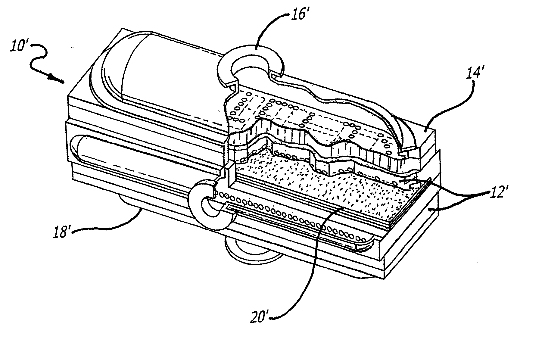
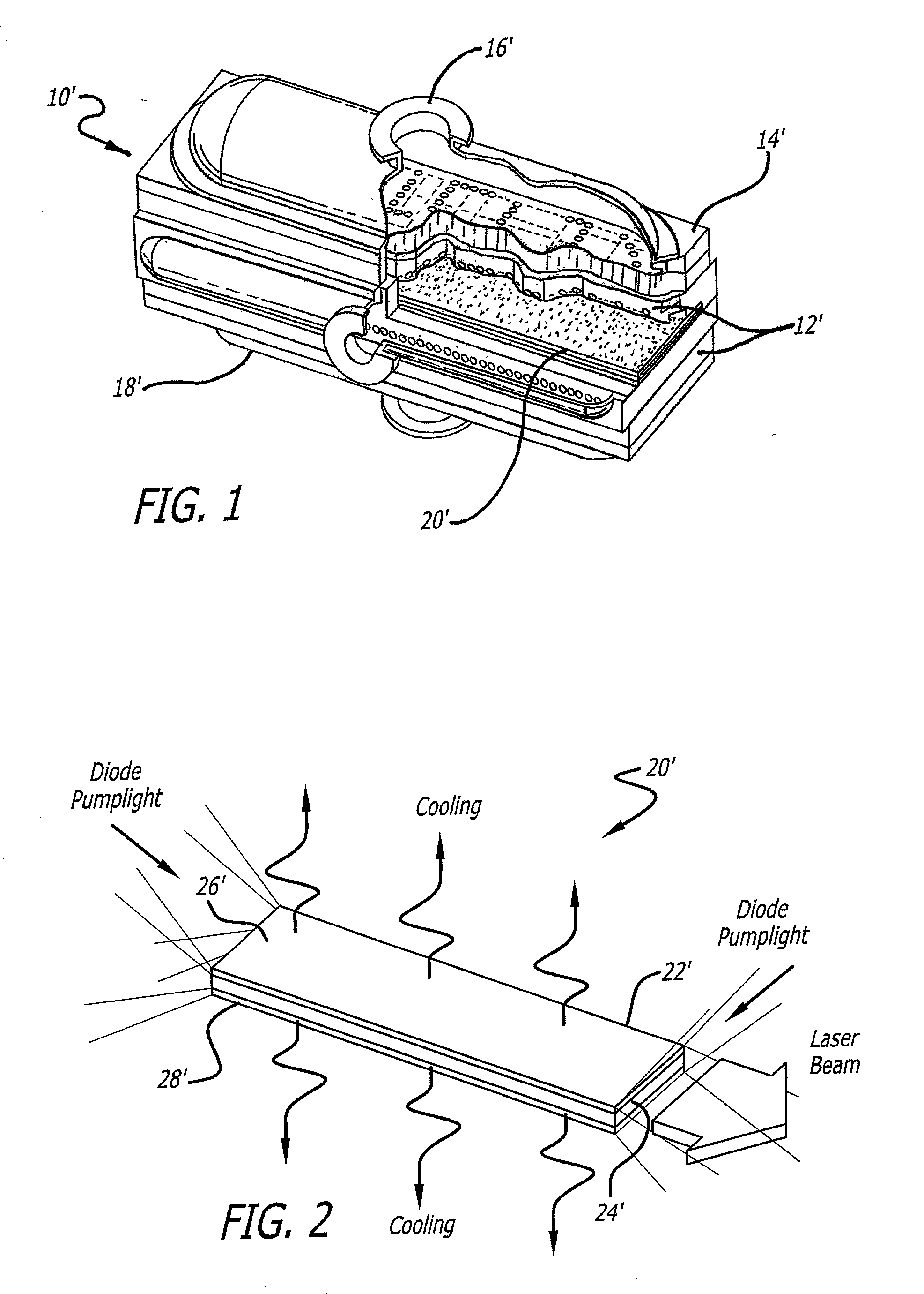
[0026] FIG. 1 is a cut-away 3-D solid model view of a multi-jet impingement-cooled slab laser pumphead designed in accordance with the teachings of the above-referenced Betin et al. application, which have been incorporated herein by reference. As discussed more fully in the Betin et al. application, the pumphead 10' includes a diffusion-bonded rec...


PUM


Abstract

A laser cooling apparatus and method. Generally, the inventive apparatus includes a mechanism for transporting sensible thermal energy from a solid state laser and for communicating waste fluorescent radiation therefrom as well. In the illustrative embodiment, the apparatus includes an optically transparent manifold (10) with an inlet port (12), an exhaust port (19) and a plurality of spray nozzles (16) therebetween adapted to direct a cooling fluid on the laser medium (20) of a laser (30). In addition, the optically transparent manifold (10) is used to permit waste fluorescent radiation to escape the confines of the laser and cooling system means such that said fluorescent radiation may be optically directed to an external heat sink such as free space.

Description

[0001] 1. Field of the Invention[0002] The present invention relates to lasers. More specifically, the present invention relates to systems and methods for cooling solid-state laser media.[0003] 2. Description of the Related Art[0004] As is well-known in the art, lasers emit waste energy in two forms: 1) sensible heat and 2) fluorescence. Sensible heat is energy that is conducted through the surface while fluorescence is waste light that is created within the medium. Sensible heat is produced by non-radiative processes in the laser medium that enable relaxation of the excited species, which may be rare-earth ions in a crystal, from a higher energy level to a lower energy level. An unavoidable portion of the sensible heat is due to the "quantum defect" which is the difference in photon energy between the pump light and the laser light. Other processes may contribute to the sensible heat, uncluding phonon-assisted quenching of the upper state population by intermediate energy levels, ...

Claims


Application Information

Patent Timeline
Patent Type & Authority Applications(United States)
IPC IPC(8): H01S3/04H01S3/042H01S3/0941
CPCH01S3/04H01S3/0941H01S3/042
Inventor BYREN, ROBERT W.GRIFFIN, WILLIAM S.BETIN, ALEXANDER A.
Owner RAYTHEON CO
Why Eureka
Try Eureka