One recurrent problem that has existed with conventional grips is that they are damaged by improper or inattentive use.
Heated grips are often damaged due to overheating when the heating elements are left at a high heating level when they should be turned off.
For example, a motorcycle rider may adjust the temperature of the grips to provide a considerable amount of heat when riding at high speed through
cold air but may forget to turn electrical current to the heating elements down or off when the rider arrives at a destination and parks the motorcycle.
If the heating elements of heated automotive vehicle handgrips are left on high for a prolonged period of time in relatively warm
ambient air, the material of which the grips is constructed will become distorted, melt, or otherwise become degraded.
This can lead to a very dangerous situation in which the
throttle control in the grip will lock up due to
distortion.
Also, since the cost of heated cycle handgrips is not inconsequential, forgetfulness in maintaining a proper temperature of the heating elements can be quite costly.
However, conventional heated handgrips for motorcycles and snowmobiles do not maintain a particular temperature.
However, conventional systems do not include control circuitry for maintaining a constant temperature, but rather only a specified level of electrical current.
If the ambient temperature about the vehicle handgrip increases, overheating of the grip can easily occur unless the user is extremely diligent in monitoring the temperature setting.
The lengthy run of wires in conventional heating current selector systems reduces the ability of a conventional heating adjustment circuit to provide an appropriate amount of heat in changing ambient conditions.
Therefore, conventional vehicle handgrip temperature setting controls have proven unsatisfactory.
In conventional systems in which an electrical resistance heating current selector is mounted upon the
chassis of the vehicle, there is a great likelihood of damage to the relatively delicate electrical components in the
heat control circuit, since the
vehicle frame is often subjected to rough treatment by the rider and by other objects in the vicinity, such as other motorcycles.
Also, when heat selector circuits are mounted on the exterior of a vehicle, such as a motorcycle, they are exposed to a great deal of
dirt,
grease,
road dust, exhaust
smoke, and other elements that are quite likely to damage the electrical circuitry.
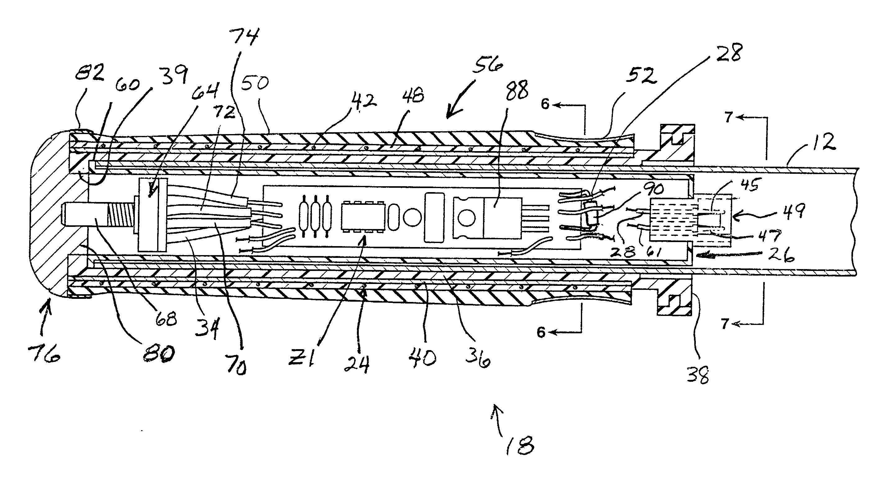
Specifically, the control circuit may be equipped with a
microprocessor that would simply be too vulnerable to damage unless housed within a heavy, bulky casing, if located on the frame of the vehicle.
More specifically, if there is a failure of one of the circuit components that results in a
short circuit to either the left-hand or right-hand electrical resistance heating element in a pair of cycle handgrips, current flow to one or both of the electrical resistance heating elements will rise to an abnormally high level above a predetermined
maximum temperature.
Conventional cycle handgrips of this type are subject to considerable damage due to inattention on the part of the rider.
For example, if power to the heating elements in conventional heated handgrips is not turned off when the vehicle is stopped and left for a period of time, the continued supply of electrical current to the electrical resistance heating element will severely damage the grip due to overheating.
If the
throttle sleeve becomes distorted due to overheating, it will not properly rotate on the vehicle handlebar.
This can lead to disastrous consequences when a rider must accelerate or decelerate rapidly to avoid traffic.
Also, unless the outer sleeve is made inordinately thick, the hand of the rider will be burned when the rider returns to the cycle and grips the outer sleeve after having inadvertently left power on to the resistance heating elements when the vehicle was parked.
This would occur if the thermistor or connector wires were to break or become shorted.

