High-speed transmission system comprising a coupled multi-cavity optical discriminator

a transmission system and optical discriminator technology, applied in the field of high-speed optical transmitters, can solve the problems of increasing system power penalties to unacceptable levels, high chirping output, and limited application of directly modulated laser transmitters

Active Publication Date: 2004-01-15
II VI DELAWARE INC
View PDF36 Cites 118 Cited by
  • Summary
  • Abstract
  • Description
  • Claims
  • Application Information

AI Technical Summary

Problems solved by technology

One of the drawbacks of a directly modulated transmitter, however, is that its output is highly chirped.
Chirped pulses become distorted after propagation through tens of km of dispersive optical fiber, increasing system power penalties to unacceptable levels.
This has limited the use of directly modulated laser transmitters to applications with limited distances of tens of km at 2.5 Gb / s as described by P. J. Corvini and T. L. Koch, Journal of Lightwave Technology vol.
For higher bit rate applications, the use of directly modulated transmitters may be limited to even shorter distances.
In the conventional directly modulated laser transmitter, chirp causes severe pulse distortion upon propagation through the optical fiber.
This is because the speed of light in the dispersive medium is frequency dependent, frequency variations of pulses may undergo different time delays, and thus the pulse may be distorted.
If the propagation distance through the medium is long as in the case of optical fibers, the pulse may be dispersed in time and its width broadened, which has an undesirable effect.
However, the steeper the transmission edges, the narrower the pass-band of the filter.
As such, Fabry-Perot filter may provide the steeper transmission edges or slope, but it does not provide the broad enough bandwidth for high bit rate applications such as 10 Gb / s.
At higher bit rates, the spectrum of the frequency modulated signal becomes more complicated and the choice of discriminators that may be used is limited.
In addition, the transient chirp that arises at the transitions between Is and Os broadens to complicate the spectrum further.
Under this performance criteria, a Fabry-Perot filter may not work because the bandwidth and slope characteristics of Fabry-Perot filters are such that the steeper the transmission edges, the narrower the pass-bandwidth of the filter.
Such limited bandwidth can severely distort a 10 Gb / s signal such that the FM modulated transmitter with a Fabry-Perot filter may not work at this bit rate.
Others have tried Fiber Bragg gratings for high bit rate applications, but fiber gratings are sensitive to temperature and require a separate package with temperature stabilization.

Method used


Image

  • High-speed transmission system comprising a coupled multi-cavity optical discriminator
  • High-speed transmission system comprising a coupled multi-cavity optical discriminator
  • High-speed transmission system comprising a coupled multi-cavity optical discriminator

Examples


Embodiment Construction

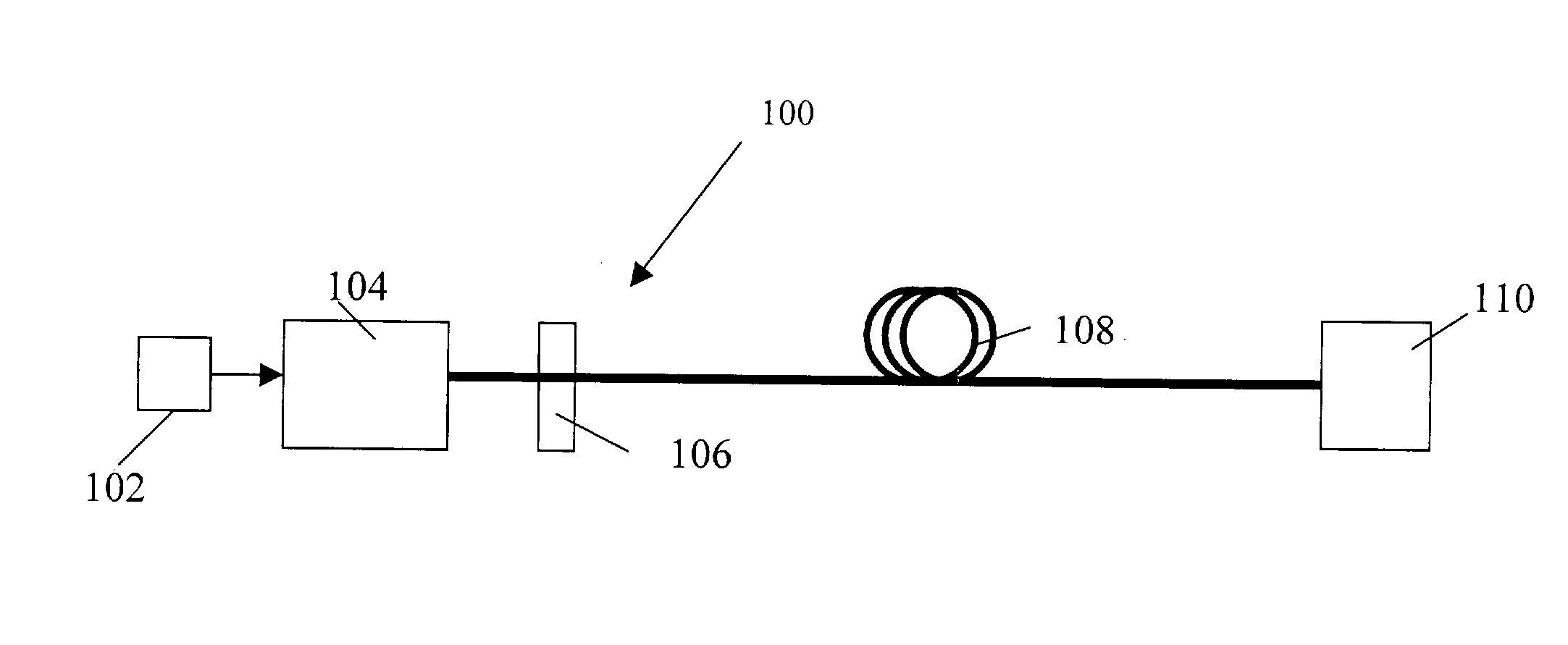
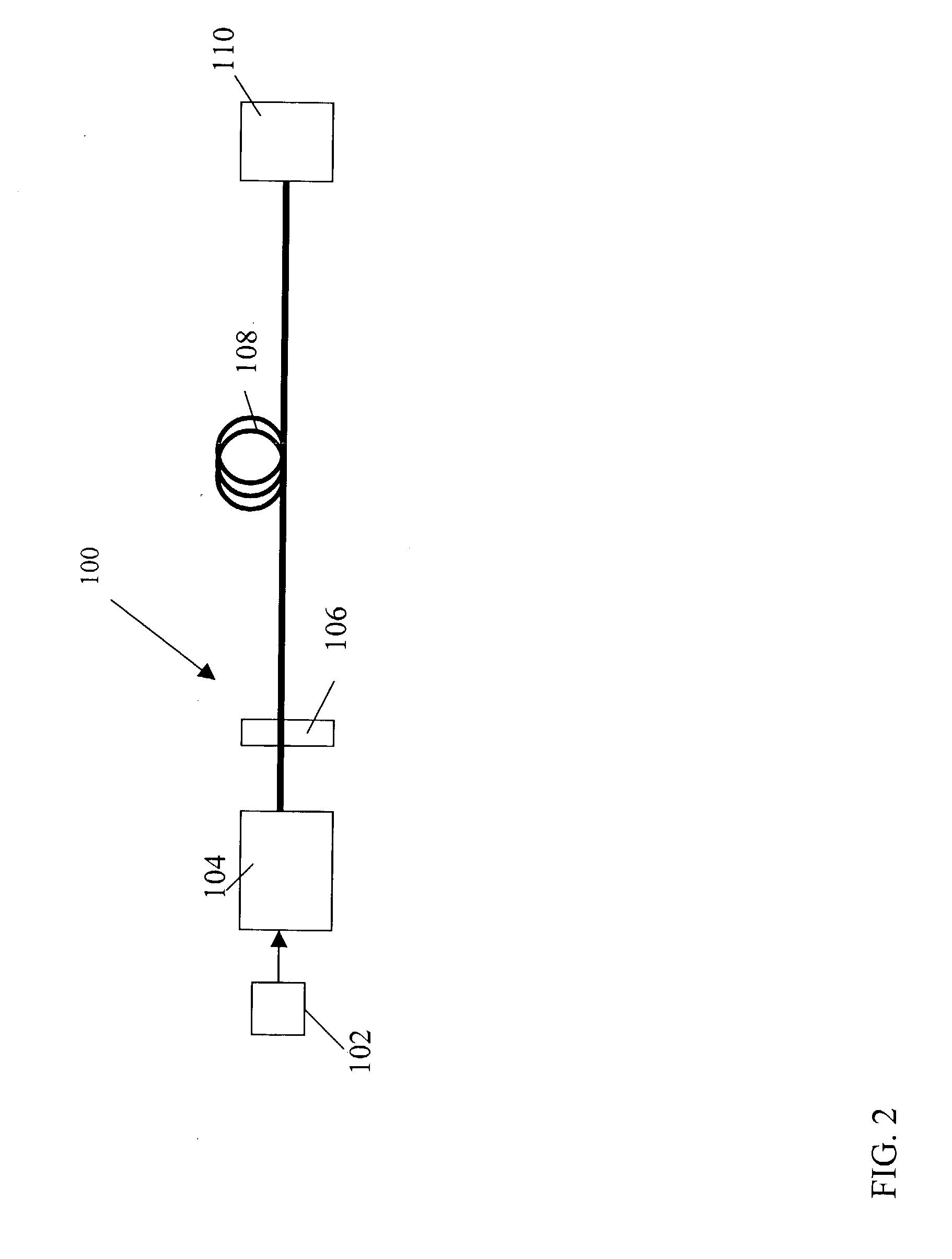
[0034] FIG. 2 illustrates a fiber optic system 100 that includes a current modulator 102 that modulates a laser source 104. The current modulator 102 may directly modulate the laser source 104. In this regard, U.S. Pat. No. 6,331,991 by Daniel Mahgereftech, issued Dec. 18, 2001 is hereby incorporated by reference into this application. The laser source 102 may be a variety of different types of lasers such as a semiconductor laser. The laser may be biased high above the threshold and the level of modulation may produce a predetermined extinction ratio, such as about 2 dB to about 7 dB. The signal from the laser may then pass through an optical discriminator 106 with a dispersion D.sub.discriminator in ps / nm and the signal from the laser may be passed through one of its transmission edges. The optical discriminator 106 may convert a partially frequency modulated (FM) signal to a substantially amplitude modulated (AM) signal. In this example, the optical discriminator 106 may be a cou...


PUM


Abstract

This invention generally relates to an optical filter for a fiber optic communication system. A coupled multi-cavity optical filter may be used, following a directly modulated laser source, and converts a partially frequency modulated signal into a substantially amplitude modulated signal. The optical filter may compensate for the dispersion in the fiber optic transmission medium and may also lock the wavelength of the laser source.

Description

1. RELATED APPLICATIONS[0001] This application claims priority to two U.S. provisional applications: (1) U.S. Application No. 60 / 395,161, filed Jul. 7, 2002; (2) U.S. Application No. 60 / 401,419, filed Aug. 6, 2002; and U.S. Patent Application entitled "Power Source for a Dispersion Compensation Fiber Optic" filed Nov. 6, 2002, which are hereby incorporated by reference.[0002] 1. Field of the Invention[0003] This invention generally relates to a high-speed optical transmitter for a fiber optic system using a coupled multi-cavity filter as a discriminator to convert frequency modulated signal to a substantially amplitude modulated signal.[0004] 3. General Background[0005] Fiber optic communication systems use a variety of transmitters to convert electrical digital bits of information into optical signals that are sent through optical fibers. On the other end of the optical fiber is a receiver that converts the optical signal to an electrical signal. The transmitters modulate the signa...

Claims


Application Information

Patent Timeline
Patent Type & Authority Applications(United States)
IPC IPC(8): G02B5/28G02B6/34H04B10/155
CPCG02B5/281G02B6/29358H04B10/504G02B6/29398G02B6/4246G02B6/29395
Inventor MAHGEREFTEH, DANIELTAYEBATI, PARVIZ
Owner II VI DELAWARE INC
Why Eureka
Try Eureka