
Implantable composite device and corresponding method for deflecting embolic material in blood flowing at an arterial bifurcation

Inactive Publication Date: 2004-01-15
SURPASS MEDICAL
View PDF5 Cites 74 Cited by
  • Summary
  • Abstract
  • Description
  • Claims
  • Application Information

AI Technical Summary

Benefits of technology

[0018] An object of the present invention is to provide, in an implantable device of the type described in the above-cited patent applications, improvements which simplify the construction, reduce the cost of manufacture, and / or increase the flexibility of the device for internal positioning.
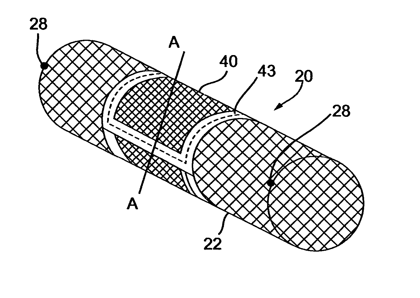
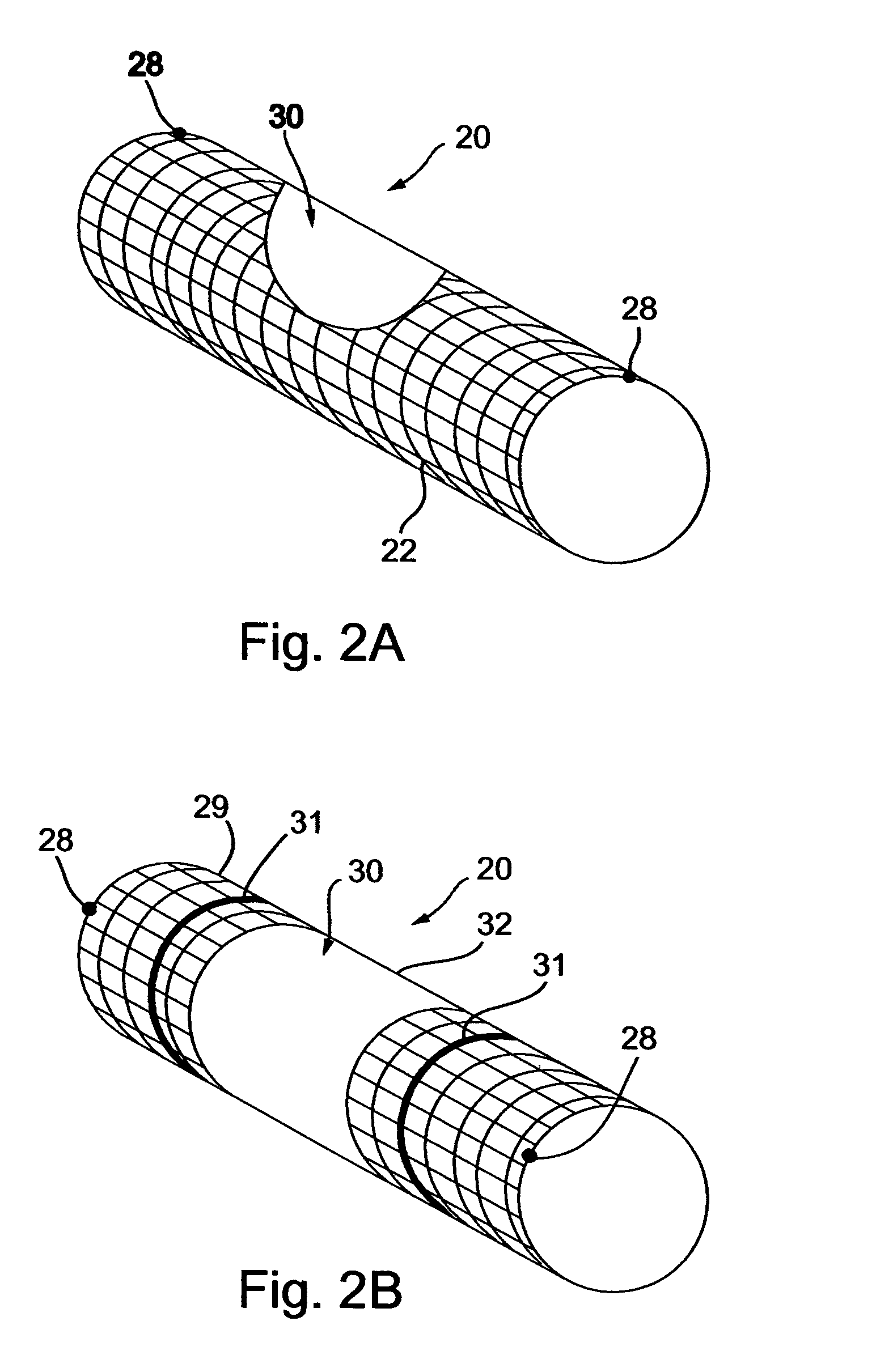
[0019] According to one aspect of the present invention, there is provided an implantable device implantable in an artery of a patient at a bifurcation thereof into a first branch supplying blood to a vital region having a high sensitivity to emboli in the blood, and a second branch supplying blood to a less vital region having a lower sensitivity to emboli in the blood; the implantable device being of tubular configuration initially of a small diameter for facilitating its introduction into and deployment through the artery to the bifurcation, and expandable to a larger diameter for implantation in the artery and the bifurcation; the implantable device comprising: a base element configured and dimensioned for anchoring the implantable device in the artery at the bifurcation; and a deflector element configured and dimensioned for covering the inlet of the first branch at the bifurcation when the implantable device is implanted in the artery; the deflector element being formed with openings therethrough of a size and configuration to deflect emboli in the blood to the second branch without blocking blood flow through the second branch or through the first branch; the base element including an anchoring portion engageable with the inner surface of the artery for anchoring the implantable device therein, and a supporting portion engageable with a surface of the deflector element for fixing the deflector element over the inlet of the first branch at the bifurcation when the implantable device is anchored in the artery; the deflector element being attached to the supporting portion of the base element to produce a composite construction.
[0027] According to another aspect of the present invention, there is provided a method of reducing the risk of a stroke in a patient, comprising: providing an implantable device as described above, configured and dimensioned for implantation in the patient's common carotid artery at its bifurcation with the internal carotid artery constituting the first branch, and the external carotid artery constituting the second branch; and implanting the implantable device in the patient's common carotid artery at the bifurcation.
[0028] According to a still further aspect of the present invention, there is provided a method for assembling an implantable device implantable in an artery of an individual at a bifurcation thereof into a first branch supplying blood to a vital region having a high sensitivity to emboli in the blood, and a second branch supplying blood to a less vital region having a lower sensitivity to emboli in the blood: selecting a base element of tubular configuration, the base element having states of different diameter, a first state being a small diameter for facilitating its introduction into and deployment through the artery to the bifurcation, and expandable to a second state being a larger diameter for implantation in the artery and the bifurcation; selecting a separate tubular deflector element comprised of elastic elements, the tubular deflector element being configured and dimensioned to cover the inlet of the first branch at the bifurcation when the implantable device is implanted in the artery, the unstretched diameter of the tubular deflector element being smaller than the diameter of the second state of the base element; inserting the base element in a contracted condition into the tubular deflector element; contracting the base element and the tubular deflector element to the first state thus facilitating its introduction into and deployment through the patient body to the bifurcation; and expanding the base element to the second state thus implantating the implantable device in the artery at the bifurcation and securing the separate tubular deflector element to the base element.

Problems solved by technology

Stroke is a leading cause of disability, death, and health care expenditure.
In fact, strokes related to cardioembolism tended to be more severe.
Carotid angioplasty, with stenting by itself, does not address additional sources of emboli, even after successful reduction of local stenosis.
However, filtering devices known in the art are designed for filtering blood flowing in the vena cava, and for stopping embolic material having a diameter of the order of centimeters, but, are unsuitable to deal with arterial embolic material, with which the present invention is concerned, especially in cases where the diameter of such material is typically of the order of down to microns.
However, when considering the possible cerebral effects of even fine embolic material occluding an artery supplying blood to the brain, the consequences may cause irreversible brain damage, or, may even be fatal.
However, a fine mesh blood filter has a higher tendency toward occlusion.
However, the ECA is a relatively non-hazardous artery because it supplies blood to superficial organs in the face and head, which are not life supporting and which receive blood supply from collateral blood vessels.
The relatively large mesh sizes employed, and, the thickness and shape of the stent struts, make them unsuitable for use as a deflector element for deflecting embolic material.

Method used


Image

  • Implantable composite device and corresponding method for deflecting embolic material in blood flowing at an arterial bifurcation
  • Implantable composite device and corresponding method for deflecting embolic material in blood flowing at an arterial bifurcation
  • Implantable composite device and corresponding method for deflecting embolic material in blood flowing at an arterial bifurcation

Examples


Embodiment Construction

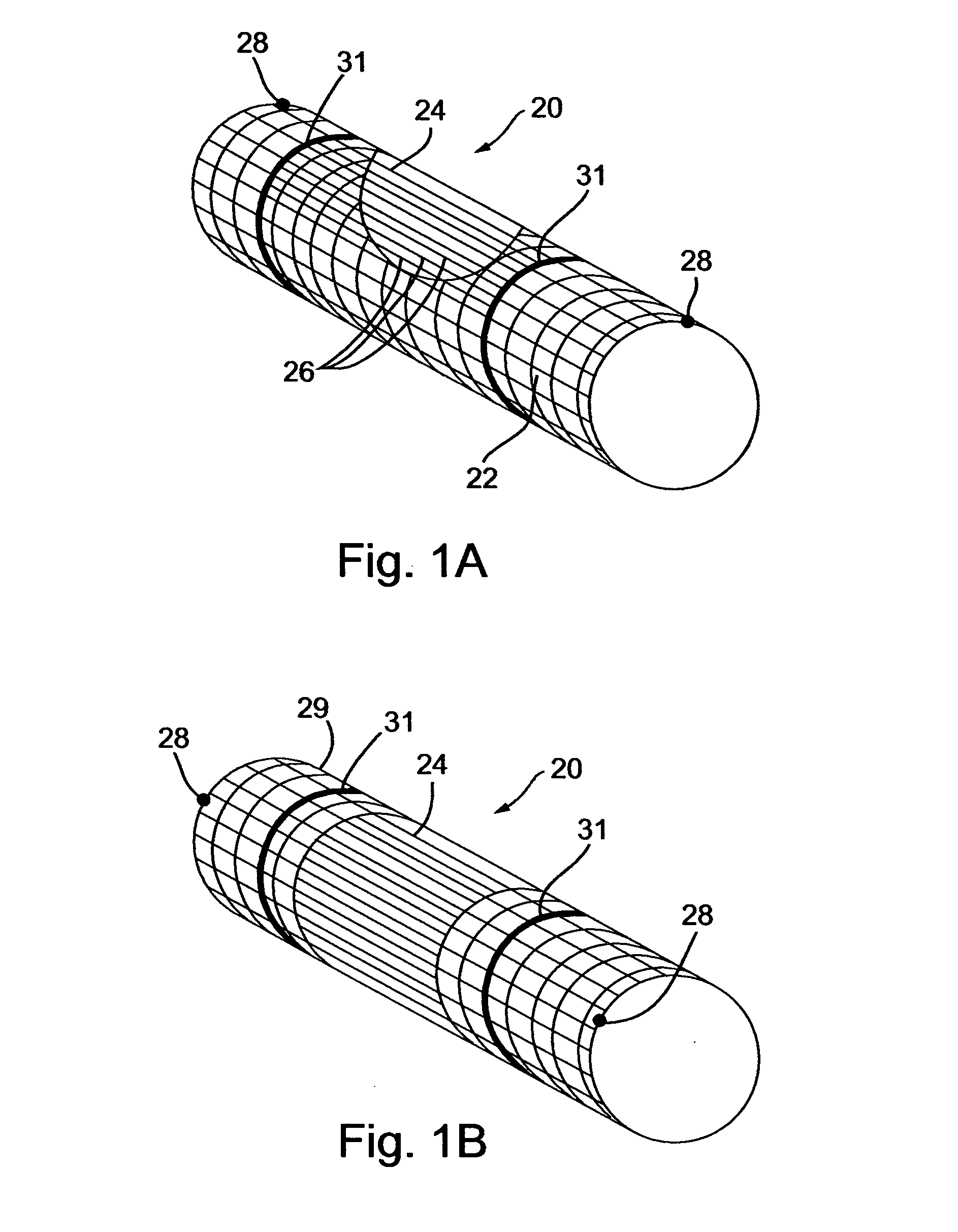
[0061] The implantable composite devices, or deflecting devices, described below are composed of two separate (principle) elements: (a) a base element, and, (b) a deflector element. Each of these elements can be produced in several forms (illustrative and non-limitative examples of which follow) and than interchangeably assembled to make the composite deflecting device. A base element for a deflecting device in accordance with a preferred embodiment of the present invention, generally designated 20, is shown in FIG. 1A. The base element of the deflecting device is made of fine wire manufactured into a net-like device having a construction suitable for expanding from a contracted position in which it is deployed through the vasculator of an individual, and expanded by means well known in the art, for example, by a balloon device coupled with a catheter. Alternatively, the base element of the device can be self-expandable, as is customary in the art with respect to peripheral stents. ...


PUM


Abstract

An implantable device particularly useful for implantation in the common carotid artery at its bifurcation with the internal carotid artery and the external carotid artery for reducing the risk of a stroke, includes a base element for anchoring the device in the artery, and a deflector element for covering the inlet of the internal carotid artery. The deflector element is formed with openings of a size and configuration to deflect emboli in the blood to the external carotid artery without blocking blood flow through the external or internal carotid arteries. The deflector element is attached to a supporting portion of the base element to produce a composite construction. In one described embodiment, the base element is a coil having two opposing ends which overlap to permit expansion for deployment in the artery, and in a second described embodiment the base element is a tube expandable for deployment in the artery.

Description

[0001] The present application is a continuation-in-part of PCT / IL02 / 00024, filed Jan. 11, 2002, which claims priority from Israel Patent Application No. 140,871 filed Jan. 11, 2001. This application is also a continuation-in-part of U.S. patent application Ser. No. 09 / 637,287, filed Aug. 11, 2000, which is a continuation-in-part of U.S. patent application Ser. No. 09 / 484,965 filed Jan. 18, 2000, now U.S. Pat. No. 6,348,063.FIELD AND BACKGROUND OF THE INVENTION[0002] The present invention relates to implantable medical devices for deflecting embolic material in blood flowing through arteries, and, more particularly, to an implantable composite device and corresponding method for deflecting embolic material in blood flowing at an arterial bifurcation. The implantable composite device, herein, also referred to as the deflecting device, featuring a unique expandable dual diameter composite structure of an expandable base element, and, a deflector element, supported and anchored by the ...

Claims


Application Information

Patent Timeline
IPC IPC(8): A61F2/06A61F2/82
CPCA61F2002/068A61F2/82
Inventor ZAFRIR-PACHTER, NITZANGRAD, YGAELRAPAPORT, AVRAHAMNISHRI, BOAZ
Owner SURPASS MEDICAL
Learn More