
Ultra high speed flip-flop

Inactive Publication Date: 2004-01-22
NORTHROP GRUMMAN SYST CORP
View PDF0 Cites 2 Cited by
  • Summary
  • Abstract
  • Description
  • Claims
  • Application Information

AI Technical Summary

Benefits of technology

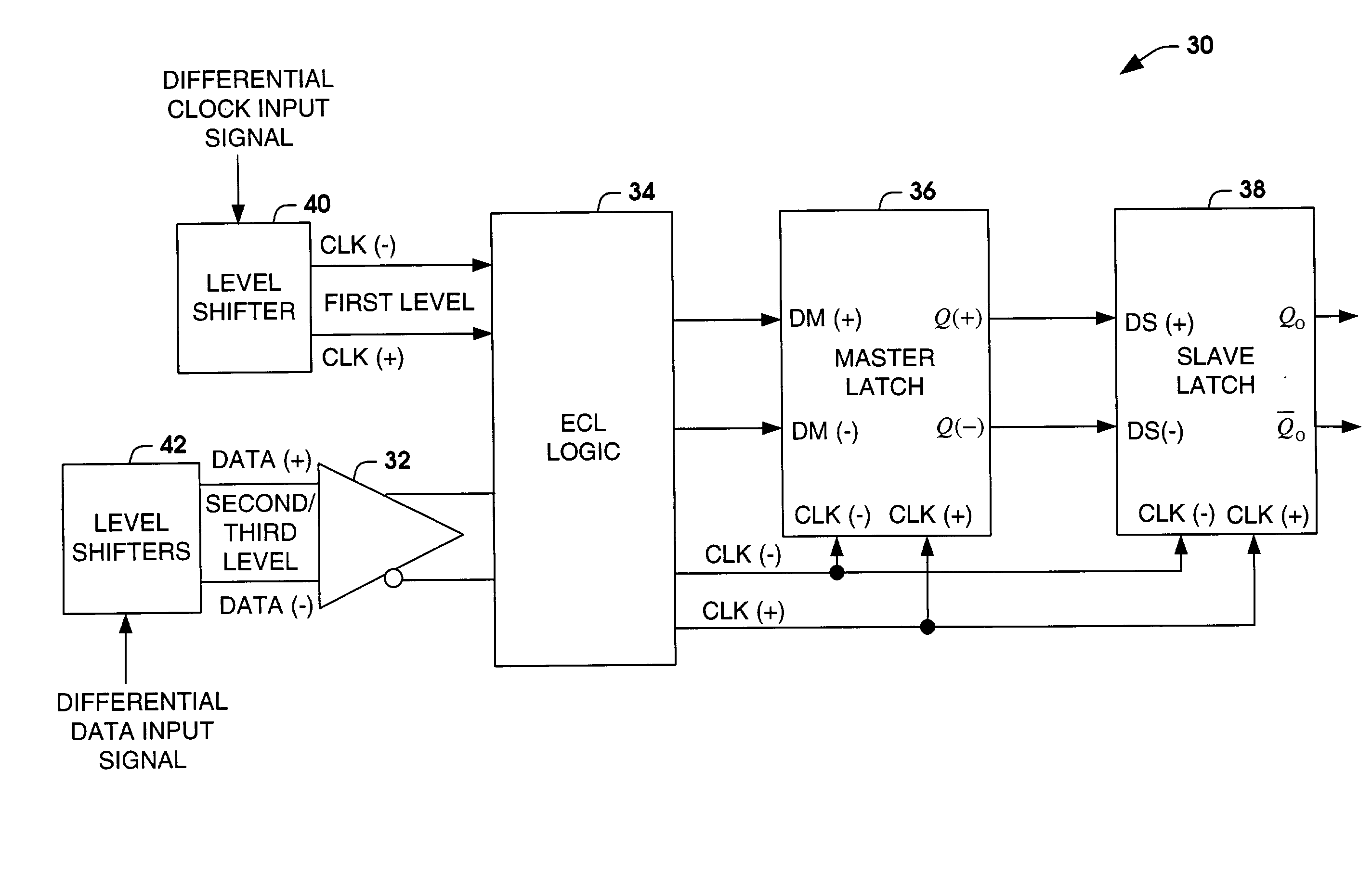
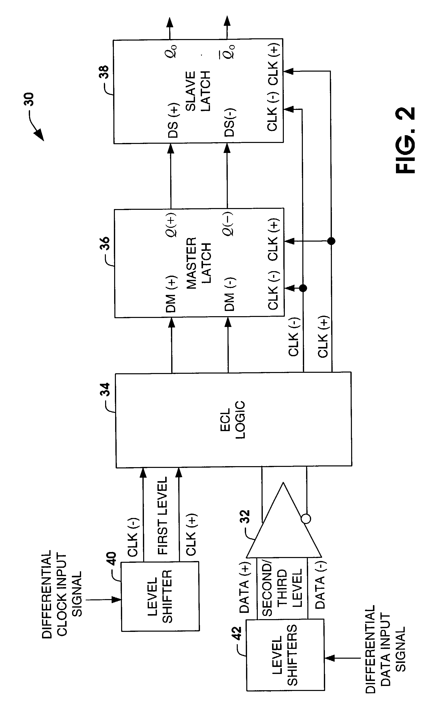
[0008] The ECL flip-flop of the present invention can operate at significantly higher data rates than conventional flip-flop circuitry. For example, data rates from about 30 GHZ to about 60 GHZ can be achieved, since the clock input signal only experiences a single level shift. The clock signal operates at about twice the frequency of the data signal. Therefore, the level shifting the data below the clock signals provides additional bandwidth to the ECL flip-flop. Additionally, distortion is mitigated by providing a closed loop differential amplifier for receiving the data signals. The ECL flip-flop can be formed from a variety of different materials (Indium Phosphide (InP), Gallium Arsenide (GaA), Silicon (Si)), such that the outer bandwidth range of the materials is extended by the configuration of the ECL flip-flop regardless of the material type.

Problems solved by technology

One major limitation of modern digital systems is the rate at which data may be transferred from one point to another.
The time required for charging and discharging various load and parasitic capacitances is quite short.
Even though, ECL is very fast in comparison to other forms of logic, it is still provided with its limitations.
Additionally, the material (e.g., Indium Phosphide (InP), Gallium Arsenide (GaA), Silicon (Si)) that the devices are constructed of has certain limitations.
As the devices begin operating at the upper range of the material, devices such as flip-flops begin to oscillate and do not operate properly.
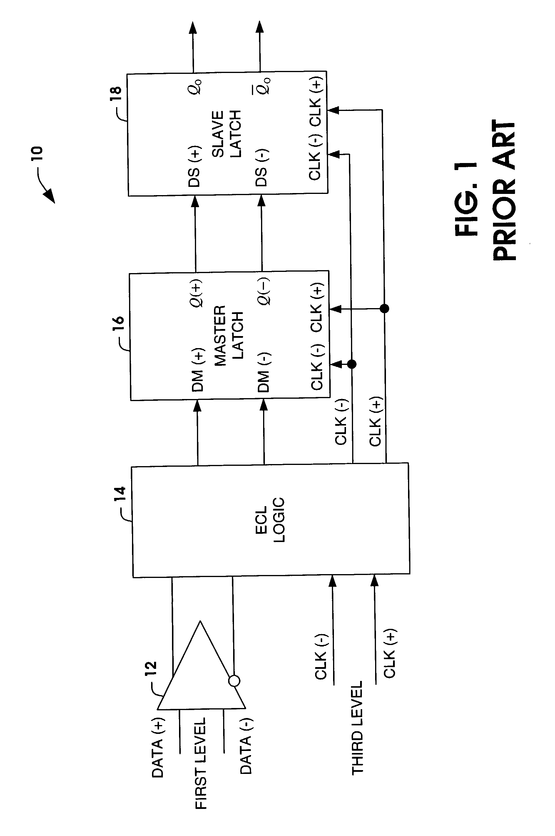
The level shifting to the different logic levels can provide additional delay to the operation of the ECL device, which can also influence the operational speed of the ECL device.
As the data is transmitted through the flip-flop 10 at very high frequencies (e.g., 30-60 GHZ), the level shifting of the clock through three cascaded emitter followers creates a stability problem causing the flip-flop to oscillate and not operate properly.
Therefore, limiting the operational speed of the flip-flop.

Method used


Image

  • Ultra high speed flip-flop
  • Ultra high speed flip-flop
  • Ultra high speed flip-flop

Examples


Embodiment Construction

[0017] The present invention provides for an ultra high speed ECL flip-flop and a method of operating the same. The ECL flip-flop of the present invention provides for clock levels that operate at logic levels above the data levels. Since the clock operates at logic levels above the data, the clock experiences level shifts that are less than the level shifts of the data. Therefore, the clock will provide a higher fidelity signal relative to the conventional clock signal. The ECL flip-flop of the present invention can operate at significantly higher data rates than conventional flip-flop circuitry. The ECL flip-flop can be formed from a variety of different materials (Indium Phosphide (InP), Gallium Arsenide (GaA), Silicon (Si)), such that the outer bandwidth range of the materials is extended by the configuration of the ECL flip-flop regardless of the material type.

[0018] FIG. 2 illustrates an ECL flip-flop 30 (e.g., ECL D-flip-flop) in accordance with an aspect of the present inven...


PUM


Abstract

An ultra high speed Emitter Coupled Logic (ECL) flip-flop is provided and a method of operating the same. The ECL flip-flop provides for clock levels that operate at logic levels above the data levels. Since the clock operates at logic levels above the data, the clock experiences level shifts that are less than the level shifts of the data. Therefore, the clock will provide a higher fidelity signal relative to the conventional clock signal. The ECL flip-flop can operate at significantly higher data rates than conventional flip-flop circuitry.

Description

[0001] The present invention relates generally to electrical circuits, and more particularly to an ultra high speed flip-flop.[0002] One major limitation of modern digital systems is the rate at which data may be transferred from one point to another. For example, in high speed computing systems where signal frequencies in excess of 100 MHZ may be found, ECL (Emitter Coupled Logic) or Current Mode Logic (CML) is often used. ECL is currently the fastest form of logic, since the active devices are arranged to operate out of saturation. ECL can provide even faster speeds by arranging that the logic signal swings are relatively small. The time required for charging and discharging various load and parasitic capacitances is quite short. ECL circuits are often preferred in high speed applications, such as telecommunication applications where increases in bit rates require increased speed of the operation of logical circuits. In these type of applications, flip-flop devices are often used ...

Claims


Application Information

Patent Timeline
IPC IPC(8): H03K19/086H03K3/012H03K3/286H03K3/2885H03K3/289
CPCH03K3/012H03K3/289H03K3/2885
Inventor YEPP, RONALD J.
Owner NORTHROP GRUMMAN SYST CORP
Learn More