Image coding method and image decoding method

a technology of image coding and decoding method, which is applied in the field of image coding method and image decoding method, can solve the problems of large amount of power for picture processing and unsuitable apparatus for high processing capability, and achieve high picture quality, high compression rate, and high efficiency

Inactive Publication Date: 2004-02-19
PANASONIC INTELLECTUAL PROPERTY CORP OF AMERICA
View PDF7 Cites 125 Cited by
  • Summary
  • Abstract
  • Description
  • Claims
  • Application Information

AI Technical Summary

Benefits of technology

0019] Thereby, since ON / OFF of filtering can be controlled so as to make full use of the processing capability of the picture coding apparatus (or the picture decoding apparatus), a CPU is used with high efficiency, and thus coding (or decoding) for high picture quality can be realized even with the same hardware resources.
0020] As described above, according to the present invention, the picture coding and picture decoding at a low bit rate (high compression rate) for high picture quality are realized, and particularly, the significant effect of improving picture quality can be achieved in picture coding processing and picture decoding processing by software under limited hardware resources, and thus it can be said that the practical value of the present invention is extremely high in these days when information communication technology and computers have become widespread.

Problems solved by technology

However, since digitalized pictures have an enormous amount of data, information compression techniques are of absolute necessity for their storage and transmission.
However, if considering the case of transmitting moving pictures via a mobile phone or the like, it is desired to minimize power consumption of a mobile apparatus as a whole in order to make available hours per charge longer, so it is not desirable for the apparatus to have high processing capability which requires a larger amount of power for picture processing.

Method used


Image

  • Image coding method and image decoding method
  • Image coding method and image decoding method
  • Image coding method and image decoding method

Examples


first embodiment

[0045] (First Embodiment)

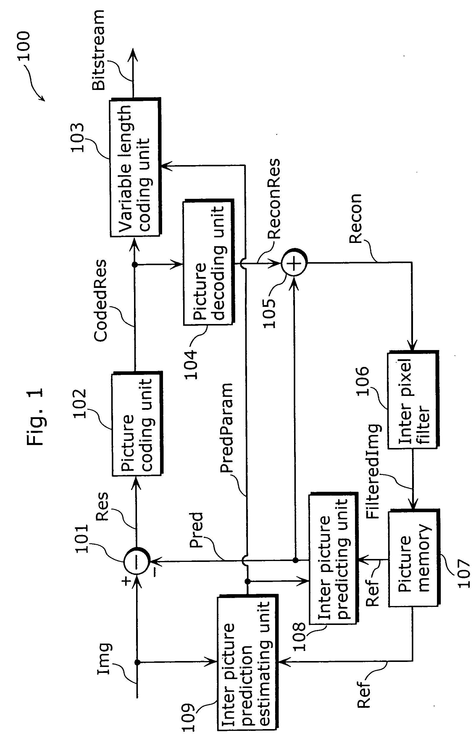
[0046] The following explains concrete embodiments of the present invention with reference to the figures. FIG. 3 is a block diagram showing the structure of a picture coding apparatus 300 according to the first embodiment of the present invention. In this figure, the same reference numbers are assigned to the same constituent elements and data as those of the conventional picture coding apparatus 100 as shown in FIG. 1 and the explanations thereof are omitted, because they have been already explained. Similarly, in the following figures, the same reference numbers are assigned to the constituent elements and data which have been already explained, and the explanations thereof are omitted. The picture coding apparatus 300 is comprised of the difference calculator 101, the picture coding unit 102, a variable length coding unit 305, the picture decoding unit 104, the adder 105, the picture memory 107, the inter picture predicting unit 108, the inter picture pr...

second embodiment

[0079] (Second Embodiment)

[0080] FIG. 8 is a block diagram showing the structure of a picture coding apparatus 500 according to the second embodiment. The picture coding apparatus 500 is different from the picture coding apparatus 300 in that as inter pixel filter processing, the former can select whether or not storing the decoded picture data Recon in the picture memory 107 as it is as reference picture data Ref. The picture coding apparatus 500 is comprised of the difference calculator 101, the picture coding unit 102, the picture decoding unit 104, the adder 105, the picture memory 107, the inter picture predicting unit 108, the inter picture prediction estimating unit 109, a switch 501, a switch 502, an inter pixel filter 503, a look up table memory unit 504, and a variable length coding unit 505.

[0081] When the value of the filter type information FilterType2 is "0", both the switch 501 and the switch 502 change the connection to the terminal "0" side to-store the decoded pict...

third embodiment

[0100] (Third Embodiment)

[0101] FIG. 14 is a block diagram showing the functional structure of a picture coding apparatus 1500 according to the third embodiment of the present invention. The picture coding apparatus 1500 is realized by a computer apparatus equipped with a CPU, a memory, a hard disk (HD) on which a program for picture coding is installed and others, and has, as functions for that, an operation console unit 1505, a pre-processing unit 1510, a subtracting unit 1512, an orthogonal transformation unit 1513, a quantization unit 1514, a variable length coding unit 1517, a post-processing unit 1520, an inverse quantization unit 1521, an inverse orthogonal transformation unit 1522, an adding unit 1524, a switching unit 1530, an inter pixel filter 1540, a picture memory 1541, a motion estimation unit 1542, a motion compensation unit 1543, a priority determining unit 1550 and a filter processing controlling unit 1560.

[0102] The operation console unit 1505 accepts an operator's...


PUM


Abstract

A picture coding apparatus (300) is a picture coding apparatus that codes a difference between picture data (Img) representing an input picture and predictive picture data (Pred) representing a predictive picture for the input picture and generates coded picture data, and includes a picture decoding unit (104) for decoding coded picture data (Img) after the picture data (Img) is coded; inter pixel filters A and B (303 and 304) for performing inter pixel filter operation for decoded picture data (Recon) obtained by the picture decoding unit (104); switches (301 and 302) for selecting one of the inter pixel filters; and an inter picture predicting unit (108) for generating the predictive picture data (Pred) for the input picture data (Img) using filtered decoded picture data (FilteredImg1), as reference picture data (Ref), obtained by the selected inter pixel filter.

Description

[0001] The present invention relates to a picture coding method, a picture decoding method, a picture coding apparatus, a picture decoding apparatus, a program for executing such methods in the form of software, and a recording medium on which the program is recorded.[0002] With the development of multimedia applications, it has become common in recent years to handle information of all sorts of media such as audio, video and text in an integrated manner. In doing so, it becomes possible to handle media integrally by digitalizing all the media. However, since digitalized pictures have an enormous amount of data, information compression techniques are of absolute necessity for their storage and transmission. On the other hand, in order to interoperate compressed picture data, standardization of compression techniques is also important. Standards on picture compression techniques include H. 261 and H. 263 recommended by ITU-T (International Telecommunication Union Telecommunication St...

Claims


Application Information

Patent Timeline
Patent Type & Authority Applications(United States)
IPC IPC(8): G06T9/00H04N19/137H03M7/36H04N19/117H04N19/127H04N19/136H04N19/156H04N19/159H04N19/172H04N19/189H04N19/423H04N19/50H04N19/503H04N19/51H04N19/577H04N19/80H04N19/82H04N19/85H04N19/91
CPCH04N19/159H04N19/176H04N19/172H04N19/46H04N19/61H04N19/117H04N19/86H04N19/156H04N19/162H04N19/182H04N19/174H04N19/82H04N19/527H04N19/14H04N19/137H04N19/51
Inventor HAGAI, MAKOTOKADONO, SHINYA
Owner PANASONIC INTELLECTUAL PROPERTY CORP OF AMERICA
Why Eureka
Try Eureka