Method for manufacturong heat exchanger

a heat exchanger and manufacturing method technology, applied in the direction of manufacturing tools, soldering devices, light and heating equipment, etc., can solve the problems of increasing material costs and weight, increasing the weight of the fin, and the total joining area of the portions to be joined is very small, so as to avoid the effect of zn erosion protection, low melting point, and smooth diffusion of zn for sacrifi

Inactive Publication Date: 2004-03-04
SHOWA DENKO KK
View PDF2 Cites 20 Cited by
  • Summary
  • Abstract
  • Description
  • Claims
  • Application Information

AI Technical Summary

Benefits of technology

0017] It is preferable to use Zn as the low melting point metal to be sprayed. In this case, since the Zn will surely exist on the surface of the flat tube, diffusion of Zn for sacrifice erosion protection can be performed smoothly. Furthermore, since the fin does not come into contact with the Zn directly, erosion of the fin due to Zn can be avoided effectively.
0018] It is preferable that the amount of low fusion metal to be sprayed falls within the range of from 3 g/m.sup.2 to 50 g/m.sup.2. This enables the brazing foil to integrally be adhered to the tube by utilizing the solidification of the low melting point metal, and can assuredly avoid bad influences such as erosion of the fin due to the existence of excessive low melting point metal. Furthermore, in cases where the amount of low fusion metal to be sprayed falls within the range of from 5 g/m.sup.2 to 15 g/m.sup.2, the aforementioned effects can be obtained more assuredly.
0019] As for the width of the brazing foil, it is preferable that the width is one fourth or more of a width of the flat tube. This enables to obtain sufficient joining strength while restraining the amount of brazing materia

Problems solved by technology

However, the total joining area of the portions to be joined is very small and that brazing materials are provided on the entire surface of the fin.
Accordingly, excessive brazing materials are consumed, resulting in increased material costs and increased weight.
Furthermore, at the time of brazing in a brazing furnace, the base metal of the fin may be eroded by the brazing materials, causing deformation thereof.
Since this deformation should be prevented, it was difficult to reduce the thickness of the base metal, resu

Method used


Image

  • Method for manufacturong heat exchanger
  • Method for manufacturong heat exchanger
  • Method for manufacturong heat exchanger

Examples


examples 1 to 8

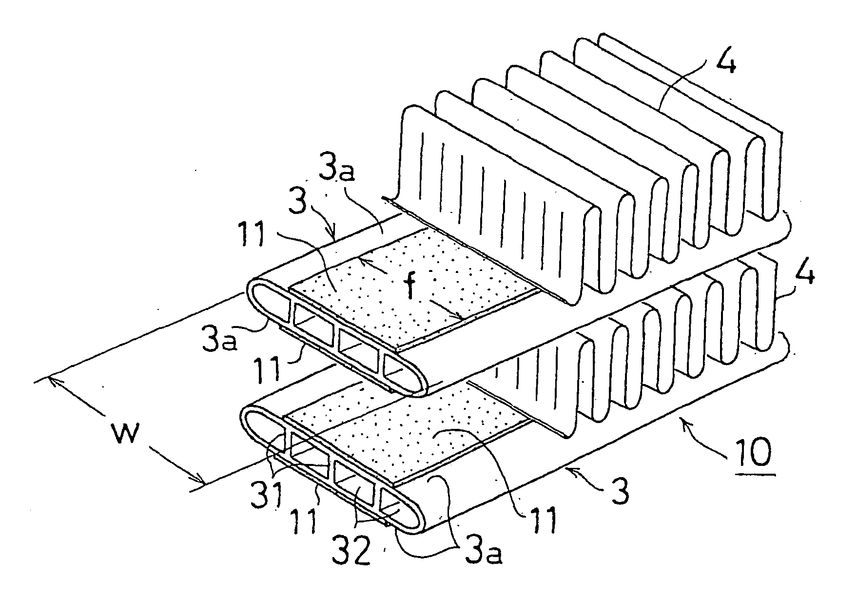
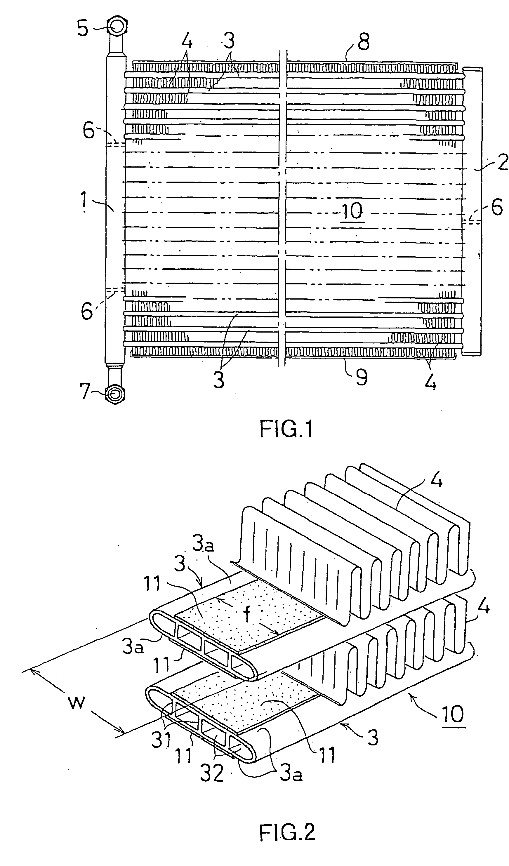
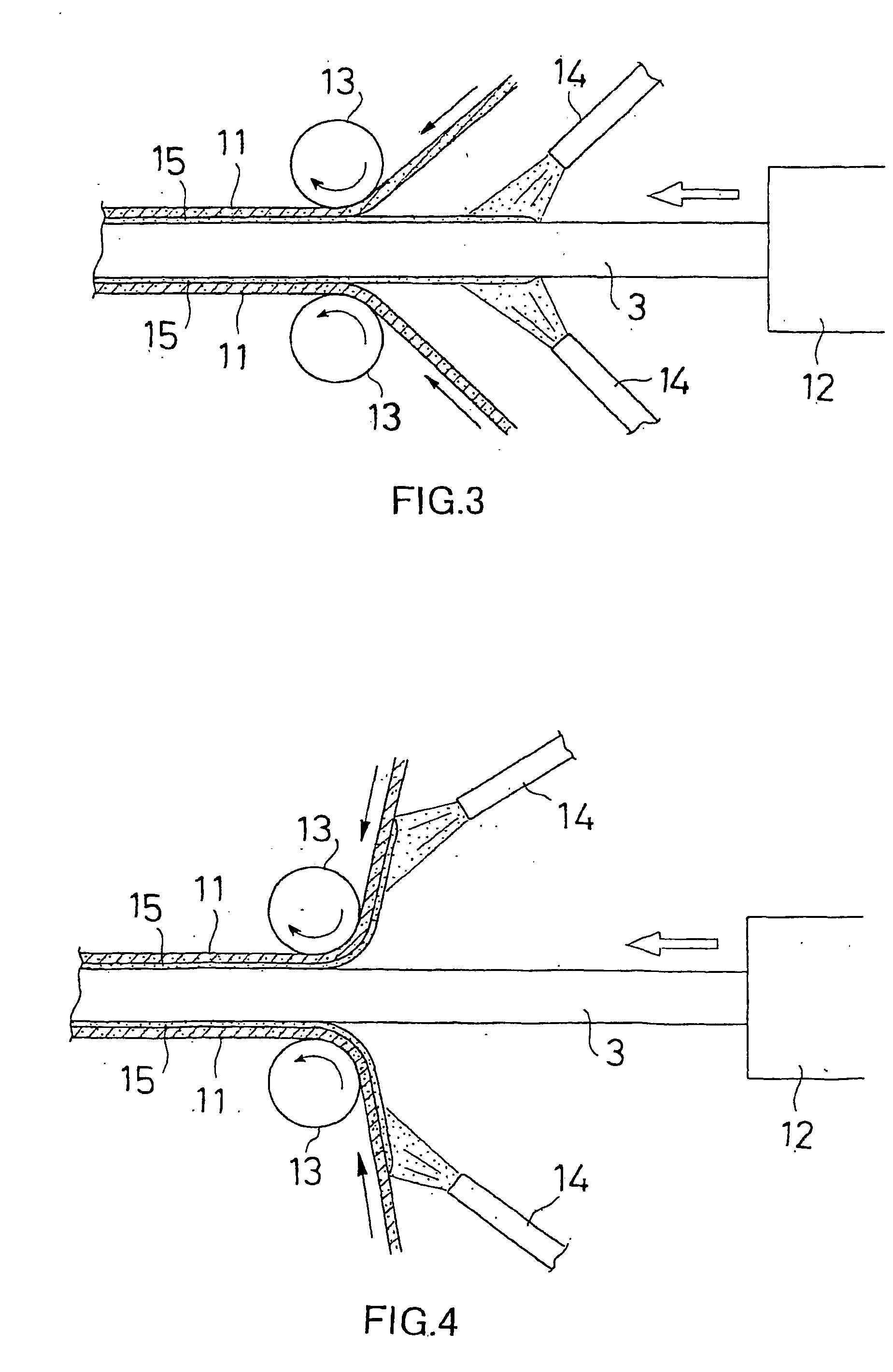
[0042] As shown in FIG. 3, on both the upper and lower flat surfaces of the aluminum flat tube 3 which was being continuously extruded from the extruding machine 12, Zn was thermally sprayed from the nozzles 14 and 14 located at the position immediately after the extrusion to form sprayed metal coatings 15 and 15. Immediately after the formation of the sprayed metal coatings 15 and 15, brazing foils 11 and 11 made of Al--Si alloy (comprising: 8 wt % of Si; and the balance Al and impurities) were adhered on the sprayed metal; coatings 15 and 15 by using pressure rollers 13 and 13. Thus, a flat tube 3 on which brazing foils 11 and 11 were adhered was obtained.

[0043] The aforementioned flat tube 3 was manufactured by extruding AA 1100 aluminum alloy at the extrusion rate of 50 m / min and the temperature of 450.degree. C. into a flat tube having a width W of 16 mm, a thickness (height) of 1.6 mm, a wall thickness of 0.3 mm and four follow portions.

[0044] The spraying of Zn was performed ...

examples 9 and 10

[0046] As the spraying metal to be thermally sprayed onto the upper and lower surfaces of the flat tube 3 immediately after the extrusion, in place of Zn used in the aforementioned examples 1 to 8, Zn--Sn alloy was used. The other conditions were the same as in the example 2. Thus, the so-called parallel flow type heat exchanger was manufactured.

example 11

[0047] As the materials of the brazing foil, Al--Si--Zn alloy (comprising: 8 wt % of Si; 3 wt % of Zn; and the balance Al and impurities) was employed. The other conditions were the same as in the example 6. Thus, the so-called parallel flow type heat exchanger was manufactured.


PUM

PropertyMeasurementUnit
Linear densityaaaaaaaaaa
Fractionaaaaaaaaaa
Fractionaaaaaaaaaa

Abstract

Low melting point metal such as Zn is sprayed onto a flat surface (3a) of an aluminum flat tube (3) to form a sprayed metal coating (15) thereon inmediately after extrusion of the flat tube. Inmediately thereafter, a brazing foil (11) is integrally adhered onto the sprayed metal coating (15). The obtained flat tube (3) with the brazing foil is combined with a corrugated fin (4) to form a temporary assembly. Then, the temporary assembly is heated at a predetermined temperature to braze the tube (3) and the fin (4) to thereby form a heat exchanger core. The low melting point metal may be sprayed on both the flat surface (3a) of the flat tube and the surface of the brazing foil (11). Thus, it becomes possible to obtain a lightweight thin fin and to decrease material costs.

Description

[0001] This application is an application filed under 35 U.S.C. .sctn.111(a) claiming the benefit pursuant to 35 U.S.C. .sctn.119(e)(1) of the filing data of Provisional Application No. 60 / 301,848 filed on Jul. 2, 2001 pursuant to 35 U.S.C. .sctn.111(b).[0002] The present invention relates to a method for manufacturing a heat exchanger made of aluminum or its alloys (hereinafter simply referred to as "aluminum") such as a condenser, an evaporator and the like for use in automobile, household or office air-conditioning systems.[0003] There is a heat exchanger having a heat exchanging core in which fins are disposed between the adjacent heat exchanging tubes. FIG. 1 shows the so-called parallel flow type heat exchanger. In the heat exchanger, a plurality of flat tubes as heat exchanging tubes are disposed in parallel between a pair of parallel headers 1 and 2 with the opposite ends thereof connected to the headers 1 and 2 in fluid communication. Between these flat tubes 3, corrugated ...

Claims


Application Information

Patent Timeline
IPC IPC(8): B23K1/00B23K1/008B23K1/20B23K35/02F28F1/02B23K35/28B23K101/14C22C18/00C22C21/00C22F1/00C22F1/04F28F1/30
CPCB23K1/0012B23K1/008B23K1/20Y10T29/4935B23K35/288B23K2201/14B23K2203/10B23K35/0233B23K2101/14B23K2103/10
Inventor ASHIDA, KOJIOSAME, YASUCHIROKAWABATA, HIROYUKIHODZUMI, SATOSHISAKAGUCHI, MASASHI
Owner SHOWA DENKO KK
Why Eureka
Try Eureka