Non-contact optical imaging system for biometric identification

an optical imaging and biometric identification technology, applied in the field of non-contact optical imaging systems for biometric identification, can solve the problems of large variations, and inability to detect contact optical biometric identification devices

Inactive Publication Date: 2004-03-04
HADDAD WALEED S
View PDF9 Cites 64 Cited by
  • Summary
  • Abstract
  • Description
  • Claims
  • Application Information

AI Technical Summary

Problems solved by technology

Each of these biometric identification devices has its own problems and strong points.
Contact optical biometric identification devices have inherent problems, including large variations in the print pattern depending on finger moistness or oiliness, variations with finger pressure, poor prints or missing sections of the print with dry or overly wet fingers, loss of contrast due to residue, or latent prints left on the platen from prior use.
In addition, there is also the security risk of identity theft due to the possibility of a user lifting any latent prints.
Many of the problems with optical readers are also present with direct reading sensors because of the need to place the finger onto the platen.
In addition, other problems with the direct-reading sensors include fragility (breaking when an object is dropped on the necessarily thin platen), damage due to electrostatic discharge, and high cost.

Method used


Image

  • Non-contact optical imaging system for biometric identification
  • Non-contact optical imaging system for biometric identification
  • Non-contact optical imaging system for biometric identification

Examples


Embodiment Construction

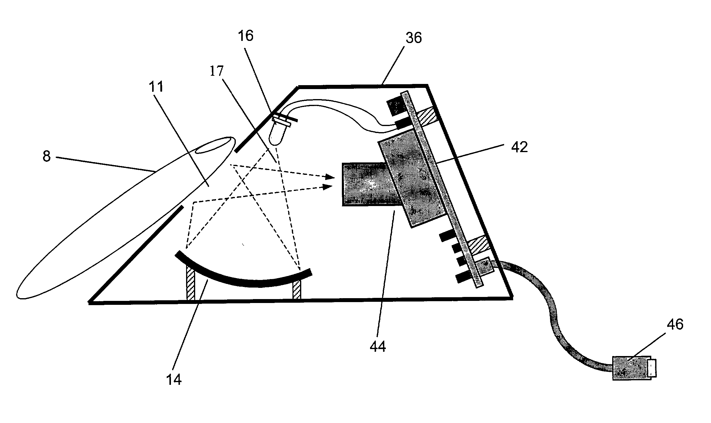
[0019] The invention produces high quality, high contrast, uniform, and consistent images of the surface features, such as characteristic ridges, of a finger or other biometric object. The basic physical property upon which the reader depends is the use of specular reflection of light to maximize the contrast of features, ridges, and height variations. Optionally, the invention uses a polarizer that filters and thereby enhances the specular reflection from the surface of the object. Optionally, the invention can also include pre-processing means for adjusting image brightness, contrast, and magnification.

[0020] In its presently preferred embodiment, the invention comprises (1) a light source that is a green light emitting diode or LED without a lens; (2) a spatial filter comprising a first stage with an aperture positioned against the light source for defining the effective size of the light source and a second stage with an aperture positioned concentric to the aperture of the firs...


PUM


Abstract

An optical system for imaging the features, ridges, and height variations of an object by exploiting the properties of specular reflection of light to maximize the contrast of the features, ridges, and height variations. The system provides a non-contact method of imaging objects suitable for biometric identification, such as the imaging of fingerprints. The system obtains the strong specular reflection using a properly shaped wave front. Optionally, the system can include a polarizer that filters and thereby enhances the specular reflection from the surface. Optionally, the system can also include pre-processing means for adjusting image brightness, contrast, and magnification.

Description

[0001] A. Field of the Invention[0002] The present invention relates to a non-contact optical imaging system for biometric identification.[0003] B. Description of Related Art[0004] There is a great need in today's age of electronic information for increased security and positive identification. For example, this includes reliable identification of purchasers at vendor sites and over the internet, identification of participants in other financial transactions, and identification in access control and anywhere sensitive information must be handled or transmitted. The growing field of biometrics provides one technological answer to this need for reliable identification. Biometric technologies measure and characterize some unique feature of a person's anatomy, which is then used to identify that person.[0005] A number of biometric identification devices already exist. These include fingerprint readers, hand geometry readers, iris imagers, retinal cameras, voice recognition, and face rec...

Claims


Application Information

Patent Timeline
Patent Type & Authority Applications(United States)
IPC IPC(8): G06K9/00
CPCG06K9/00033G06V40/1312
Inventor HADDAD, WALEED S.
Owner HADDAD WALEED S
Why Eureka
Try Eureka