With ignition assisted discharge lamp

a discharge lamp and assisted discharge technology, which is applied in the direction of electric discharge lamps, discharge tubes luminescnet screens, electrical equipment, etc., can solve the problems of long ignition delay after the application of voltage to the electrodes of the lamps, and the lamp can only be ignited with a significantly increased voltage compared with normal operation

Inactive Publication Date: 2004-03-11
PATENT TREUHAND GESELLSCHAFT FUR ELECTRIC GLUEHLAMPEN MBH
View PDF7 Cites 10 Cited by
  • Summary
  • Abstract
  • Description
  • Claims
  • Application Information

AI Technical Summary

Problems solved by technology

What is disadvantageous, however, is the long ignition delay after the application of the voltage to the electrodes of the lamp if the lamp is in darkness, for example within an LCD display.
After some time in darkness, it can even happen that the lamp can only be ignited with a sign

Method used


Image

  • With ignition assisted discharge lamp
  • With ignition assisted discharge lamp

Examples


Embodiment Construction

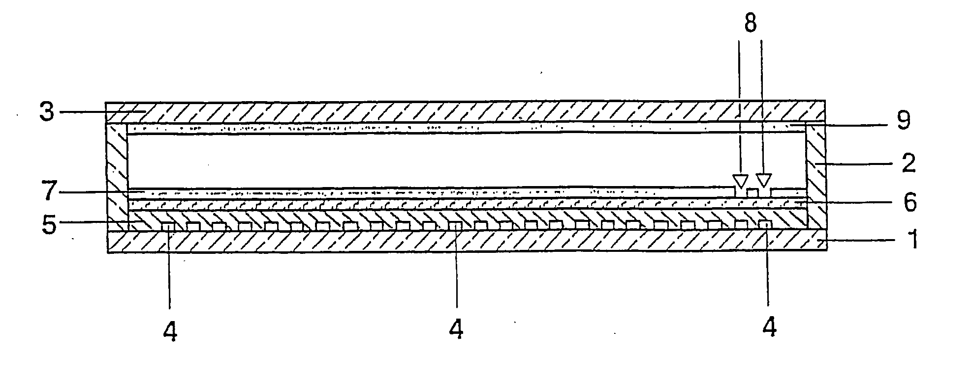
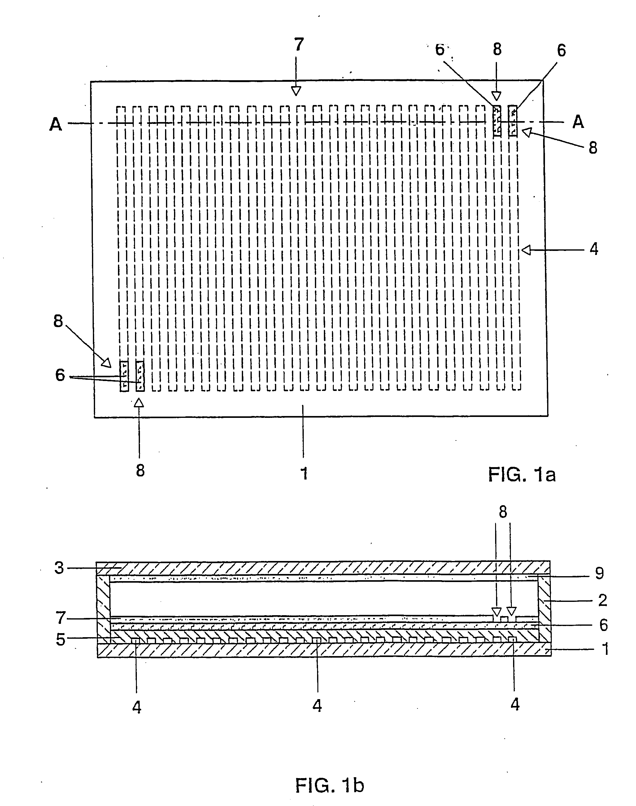
[0026] FIGS. 1a and 1b show a diagrammatic plan view of a baseplate 1 of a flat lamp and, respectively, a cross section through a complete flat lamp based on the baseplate 1 in FIG. 1a along the line AA.

[0027] The baseplate 1 is connected to a front plate 3 by means of a peripheral frame 2 to form a gastight flat discharge vessel. A gas filling of xenon with a filling pressure of 10 kPa is situated within the flat lamp. Numerous strip-like electrode tracks 4 made of conductive silver solder having a width of approximately 1 mm and a thickness of approximately 10 .mu.m are printed on the inner wall of the baseplate 1. Their distance from one another is approximately 6 mm. For operation, the strip-like electrodes 4 are alternately connected to one of the two poles of a voltage source which supplies a pulse voltage sequence. As a result, numerous partial discharges form between the directly adjacent electrode tracks. In this case, the partial discharges start essentially beside one ano...


PUM


Abstract

A dielectric barrier discharge lamp having electrodes arranged on the wall of the discharge vessel has a VUV/VIS reflection layer (6) made of a material with a high secondary electron emission coefficient on at least a part of the inner wall of the discharge vessel. A luminescent material layer (7) is in turn applied on the VUV/VIS reflection layer (6). Moreover, at least one partial region (8) without luminescent material is provided in the luminescent material layer (7), this at least one partial region (8) partially uncovering the underlying VUV/VIS reflection layer (6) and additionally being arranged at least in direct proximity to one or more electrodes (4) of the lamp. As a result, the ignition behavior of the lamp is improved, in particular during ignition in darkness.

Description

[0001] The invention relates to a dielectric barrier discharge lamp in accordance with the preamble of claim 1.[0002] Dielectric barrier discharge lamps are sources of electromagnetic radiation based on dielectrically impeded gas discharges.[0003] The discharge vessel is usually filled with a noble gas, for example xenon, or a gas mixture. So-called excimers are formed during the gas discharge, which is preferably operated by means of a pulsed operating method described in U.S. Pat. No. 5,604,410. Excimers are excited molecules, e.g. Xe.sub.2*, which emit electromagnetic radiation upon returning to the generally unbonded ground state. In the case of Xe.sub.2*, the maximum of the molecular band radiation lies at approximately 172 nm (VUV radiation).[0004] The present invention relates to a dielectric barrier discharge lamp having a luminescent material layer which is applied on the inner wall of the discharge vessel and serves for converting the invisible VUV radiation into visible (...

Claims


Application Information

Patent Timeline
IPC IPC(8): H01J61/54H01J65/00H01J65/04
CPCH01J65/046H01J61/545H01J65/04
Inventor DOLL, GERHARD
Owner PATENT TREUHAND GESELLSCHAFT FUR ELECTRIC GLUEHLAMPEN MBH
Why Eureka
Try Eureka