
Display manufacturing apparatus and display manufacturing method

a technology of display manufacturing and manufacturing method, which is applied in the manufacture of electrode systems, electric discharge tubes/lamps, instruments, etc., can solve the problems of increased parts and additional problems in common use, and achieve the effect of accurate control and high precision

Active Publication Date: 2004-03-18
KATEEVA
View PDF10 Cites 31 Cited by
  • Summary
  • Abstract
  • Description
  • Claims
  • Application Information

AI Technical Summary

Benefits of technology

The patent text describes a display manufacturing apparatus and a method for controlling the same. The technical effects of the invention include simplifying the structure of the apparatus by integrating multiple parts, reducing the number of parts, and improving the common use of the apparatus. The invention also provides a method for adjusting the driving voltage to optimize the discharge characteristics of liquid drops, resulting in improved manufacturing efficiency and consistent quality. The invention also includes a display device using the color filter manufacturing apparatus and a method for controlling the same. Overall, the invention simplifies the manufacturing process and improves the quality of display devices.

Problems solved by technology

However, when the exclusive nozzle or head is separately provided, the structure of the apparatus gets so complex as to result in an increase in the number of parts.
Further, it may bring about additional problems in the common use.

Method used


Image

  • Display manufacturing apparatus and display manufacturing method
  • Display manufacturing apparatus and display manufacturing method
  • Display manufacturing apparatus and display manufacturing method

Examples


second embodiment

[0252] Next, a description will be made of the present invention. FIG. 27 is a cross-sectional view of essential parts illustrating a display region of an organic EL display device (hereinafter, simply referred to as a display device 106), a type of a display in the present invention.

[0253] The display device 106 is generally configured with a circuit element part 107, a light-emitting element part 108 and a cathode 109 laminated on a substrate 110.

[0254] In the display device 106, the light emitted from the light-emitting element part 108 to the substrate 110 is transmitted through the circuit element part 107 and the substrate 110 and emitted to the observer's side. On the other hand, the light emitted to the side opposite to the substrate 110 from the light-emitting element part 108 is reflected by the cathode 109, transmitted through the circuit element part 107 and the substrate 110 and emitted to the observer's side.

[0255] A base protective film 111 of a silicon oxide film is ...

first embodiment

[0280] Similar to the colored layer formation step, the hole injection / transport layer formation step, as shown in FIG. 21 is performed by undergoing the liquid material discharge step (S11), the hitting amount detection step (S12), the correction amount acquiring step (S13) and the liquid material supplementation step (S14) in sequence. Furthermore, since a detailed description about the respective steps of S11 to S 14 is made in the above first embodiment, the description thereof will be omitted.

[0281] As shown in FIG. 31, in the liquid material discharge step (S11), the first composition including the hole injection / transport layer forming material is implanted into the pixel regions (that is, the openings 22) of the display device substrate 106' as a predetermined amount of liquid drops. In this case, since the waveform of driving pulses is also set as described above, the discharge amount or flying speed of a liquid drop can be optimized to hit a predetermined amount of the fir...

third embodiment

[0304] Next, the present invention will be described. FIG. 37 is an exploded, perspective view of essential parts illustrating a plasma type display device (hereinafter, simply referred to as a display device 125), a type of a display in the present invention. Furthermore, the display device 125 is shown in the drawing with a part thereof being cut out.

[0305] The display device 125 is generally configured with first and second substrates 126, 127 arranged to face each other and an electric discharge display part 128 to be formed between the two substrates. The electric discharge display part 128 is configured with a plurality of electric discharge chambers 129. Among the plurality of electric discharge chambers 129, three electric discharge chambers 129 of a red electric discharge chamber (129R), a green electric discharge chamber (129G) and a blue electric discharge chamber (129B) are taken into a group to be configured into one pixel.

[0306] Address electrodes 130 are formed at a p...


PUM

PropertyMeasurementUnit
weightaaaaaaaaaa
weightaaaaaaaaaa
widthaaaaaaaaaa

Abstract

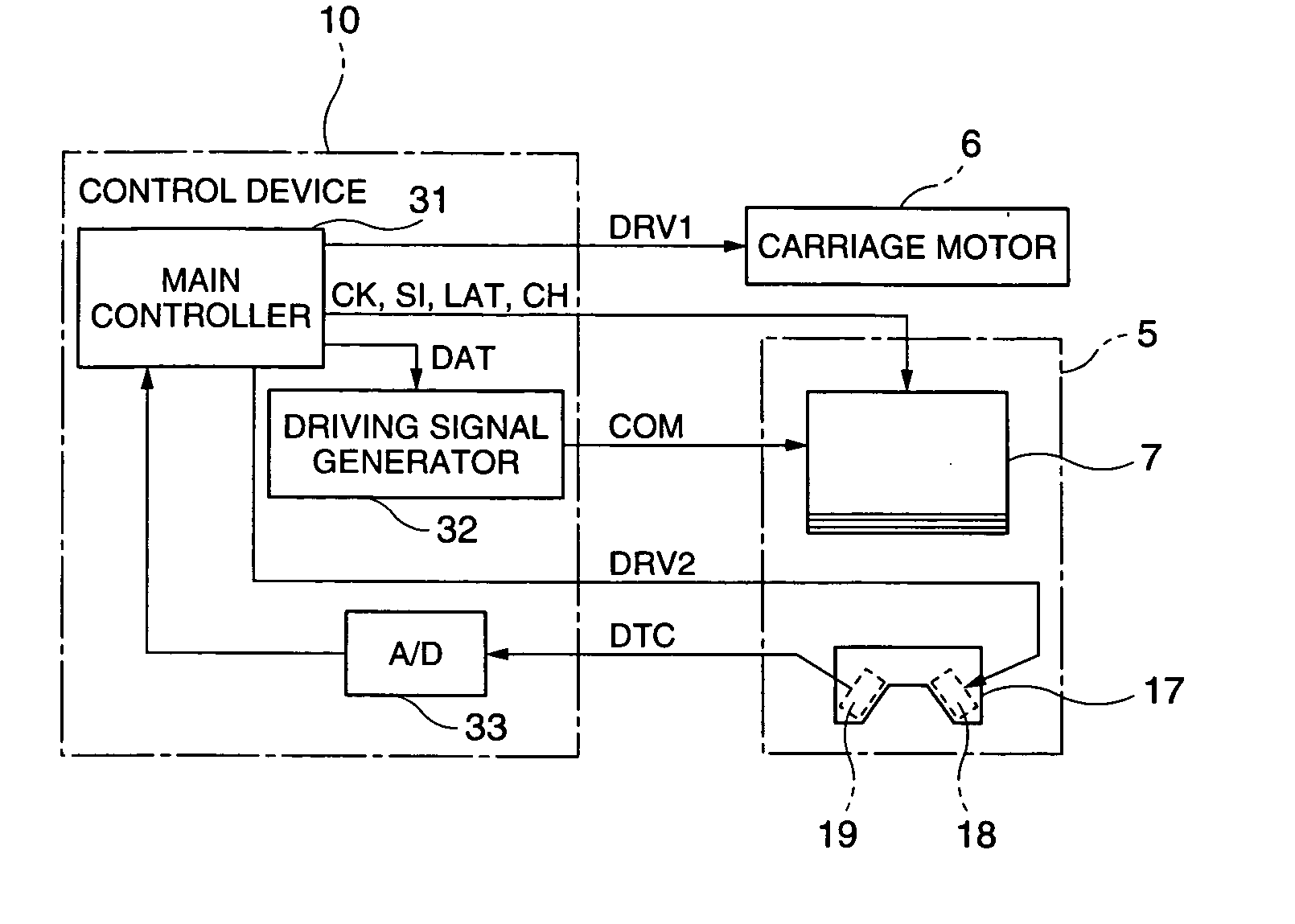
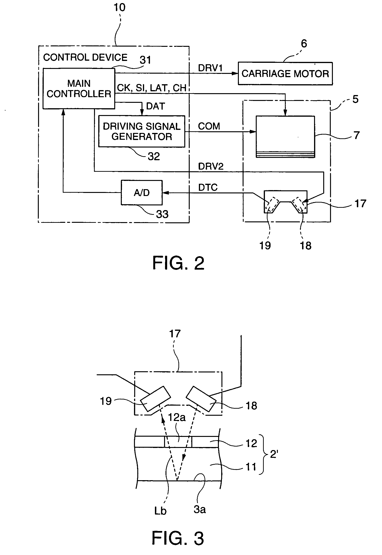
A carriage 5 is provided with an injection head 7 to discharge an amount of liquid drops according to the supplied driving pulses and a liquid material sensor 17 to detect the ink amount hit at a filter substrate at each pixel region. A main controller 31 determines a waveform of the driving pulses capable of discharging the short amount of liquid drops according to a level of a detection signal from the liquid material sensor 17 and outputs the determined information on the waveform of the driving pulses to driving signal generator 32. The driving signal generator 32 generates driving pulses according to the received information on the waveform and outputs it to the injection head 7. The injection head 7 adjusts an ink amount at the corresponding pixel region to the target amount of liquid material by injecting the short amount of liquid drops to the corresponding pixel region.

Description

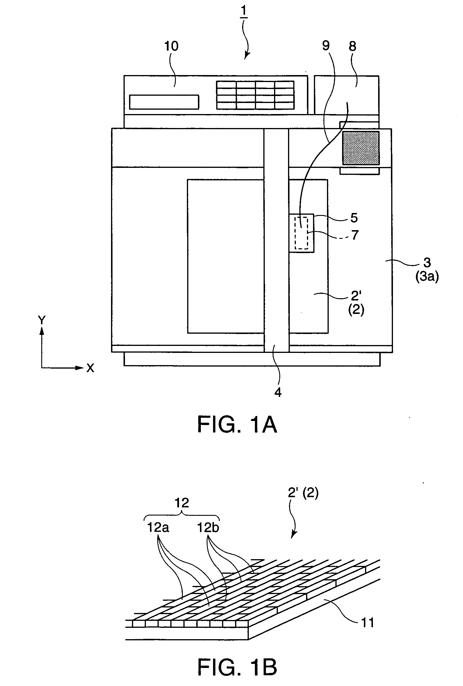
[0001] The present invention relates to a display manufacturing apparatus and a display manufacturing method for manufacturing a variety of displays such as a color filter for a liquid crystal display device, an electroluminescent display device and the like by discharging liquid material.[0002] In order to manufacture a color filter for a liquid crystal display device, an electroluminescent display device or a plasma display device, there has been appropriately used an injection head (for example, an ink jet head) by which a liquid state material (liquid material) can be discharged in a liquid state. In a display manufacturing apparatus using an injection head, for example, a color filter is manufactured by injecting liquid material discharged out of nozzle openings to a plurality of pixel regions provided on the surface of a substrate. However, a variation in the characteristics at every nozzle opening may results in defects such as color nonuniformity or decoloring at the pixel r...

Claims


Application Information

Patent Timeline
Patent Type & Authority Applications(United States)
IPC IPC(8): B05D1/26B05C5/00B41J2/01B41J2/045B41J29/393G02B5/20H01J9/02H01J11/12H01J11/22H01J11/24H01J11/26H01J11/34H01J11/42H01L51/50H05B33/10
CPCB41J2/0456B41J2/04581B41J2202/09B41J2/04593B41J29/393B41J2/04588G02B5/20
Inventor TAKAHASHI, TOMOAKISAKAI, HIROFUMI
Owner KATEEVA
Learn More