Firewall interface configuration and processes to enable bi-directional VoIP traversal communications

Inactive Publication Date: 2004-03-25
FORTINET
View PDF37 Cites 131 Cited by
  • Summary
  • Abstract
  • Description
  • Claims
  • Application Information

AI Technical Summary

Benefits of technology

0020] It is the object of the present invention to provide a new and improved interface configuration and processing scheme for a network protection gateway (NPG) to manage packets transmission. The network protection gateway provides both network layer and application layer protection, and through their content-aware proxy architecture, understand a

Problems solved by technology

A technical difficulty is still faced by those who apply the Internet Protocol for voice communication by sending voice messages as digitized data packets on Internet, commonly known as the VoIP technologies, when the sender or the receiver are protected by a firewall protection system.
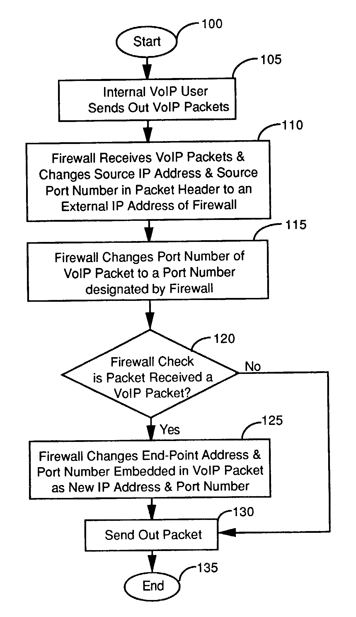
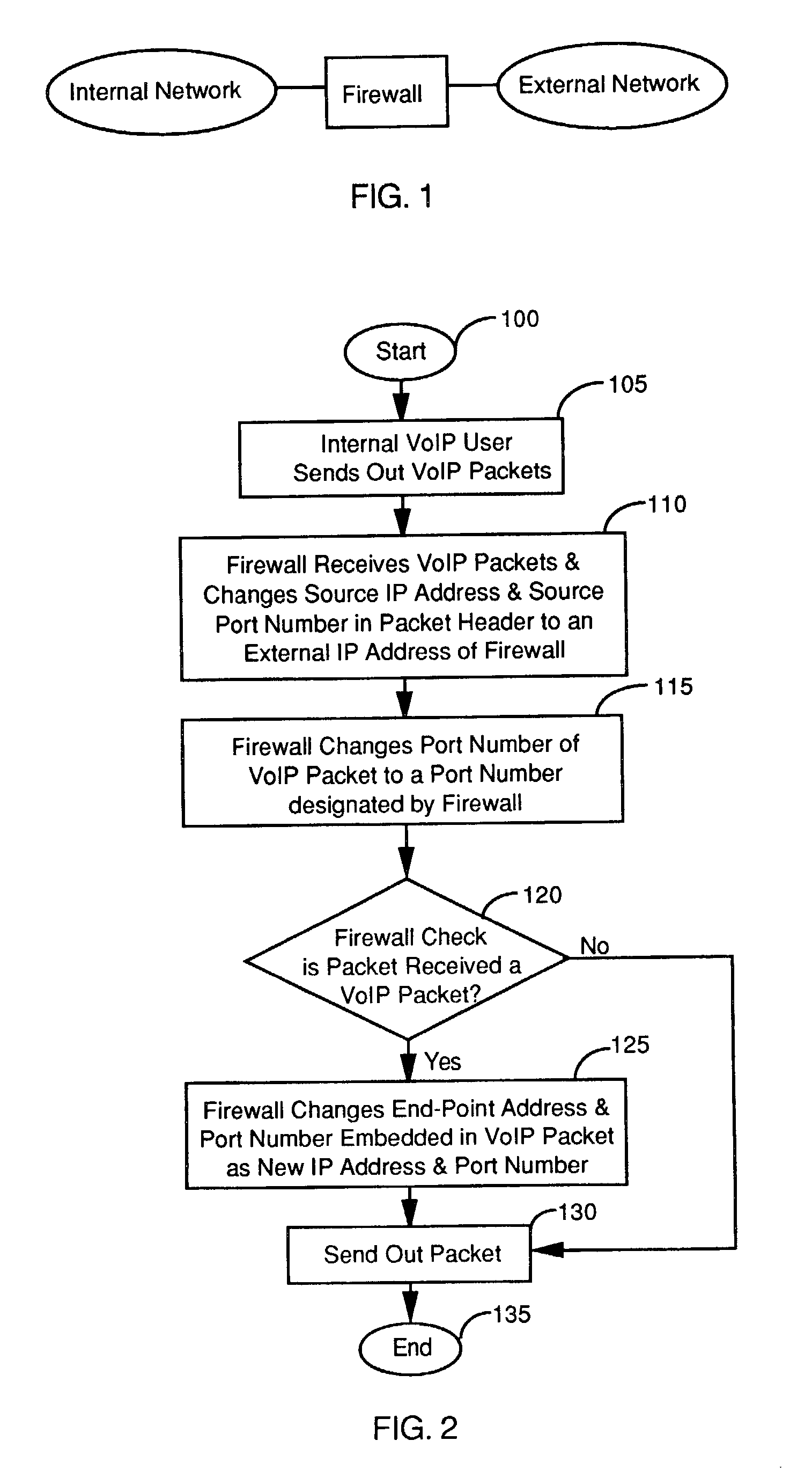
However, once the sender's identification, i.e., the source IP address and port number of the sender, is translated and changed by the firewall, a return packet in response to the sender's VoIP packets can only return to the firewall and would be unable to reach the sender.
Due to the mismatches, the VoIP communication cannot be successful.
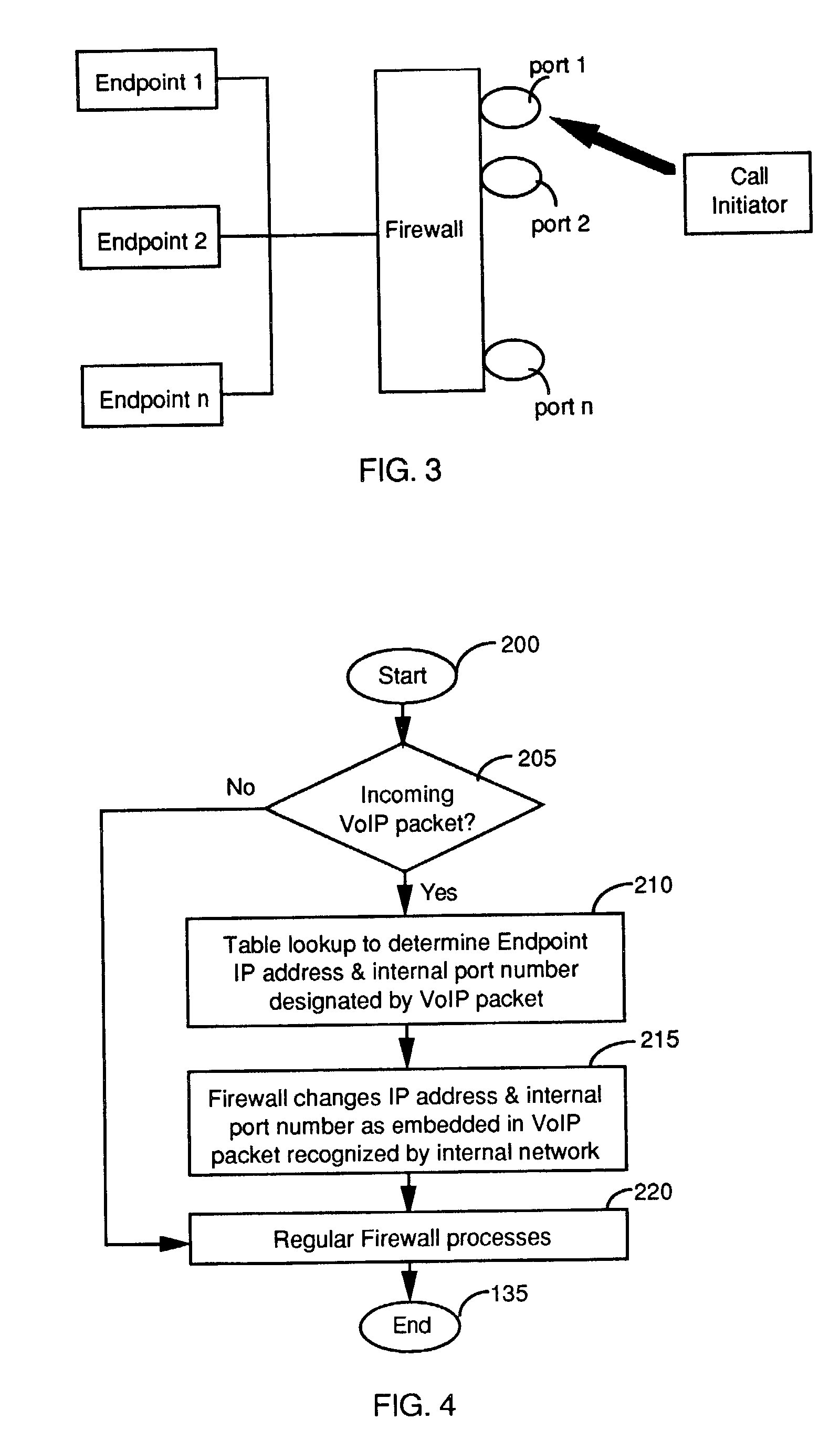
Furthermore, for the inbound VoIP communications, because the internal host's IP addressees are hidden from the public network, VoIP traffic when designate the IP address and the port number of an internal IP address cannot reach individual end point by their IP address, thus an incoming call cannot be made.
However, since only one port is used, a call can only be made to one end point inside firewall using the conventional method.
However, widespread use of VoIP is at odds with conventional security technology

Method used


Image

  • Firewall interface configuration and processes to enable bi-directional VoIP traversal communications
  • Firewall interface configuration and processes to enable bi-directional VoIP traversal communications
  • Firewall interface configuration and processes to enable bi-directional VoIP traversal communications

Examples


Example

[0033] Example 1 as described below provides a specific implementation by the Assignee of this Application. The Example is provided to further illustrate a network protection gateway (NPG) that applies an intelligent VoIP-aware network address translation (NAT) solution while enable a comprehensive network protection functions in a single unit. The intelligent NPG is implemented as an application specific integrated circuit ASIC-based real-time anti-virus protection, connection filtering, firewall, VPN, intrusion detection, and traffic-shaping device. The comprehensive intelligent NPG takes advantage of a "application-aware" feature of the device to implement the techniques disclosed in this invention that provide "VoIP-aware" NAT services.

EXAMPLE 1

[0034] The device of this Example recognizes H.323 messages based on the standard port 1720-port address and parse the body of H.323 messages When it recognizes specific H.323 messages that carry the RTP / RTCP addresses, the NPG device cre...


PUM


Abstract

A firewall for interfaced between an internal and an external networks. The firewall includes a VoIP processor for detecting an outgoing VoIP packet sent from the internal network for changing data in a header of the VoIP packet and also changing data contents in the VoIP packet corresponding to data changed in the header to enable a bi-directional VoIP communication. In a preferred embodiment, the VoIP processor changes a source IP address and a port number in the header of the VoIP packet and also changes the data contents in the VoIP packet corresponding to the source IP address and the port number changed in the header to enable a bi-directional VoIP communication. In another preferred embodiment, the firewall further includes an external VoIP interface comprising a plurality of VoIP ports for receiving multiple incoming VoIP packets each designated with one of the VoIP ports. And, the VoIP processor further includes a VoIP port versus internal address table for identifying an internal address in the internal network for directing each of the incoming VoIP packets to the internal address identified.

Description

[0001] 1. Field of the Invention[0002] This invention generally relates to the management and processes of the network communication packet implemented with a firewall. More particularly, this invention is related to a new interface configuration and processing scheme for enhancing bi-directional VoIP communication traversing the firewall without degrading the level of protections provided by the firewall.[0003] 2. Descriptions of the Reference Art[0004] A technical difficulty is still faced by those who apply the Internet Protocol for voice communication by sending voice messages as digitized data packets on Internet, commonly known as the VoIP technologies, when the sender or the receiver are protected by a firewall protection system. Specifically, several popular VoIP signaling protocols such as MGCP, SIP and H323 are commonly implemented. All these different types of protocols are implemented with the data relating to the end point address embedded as part of the data content tr...

Claims


Application Information

Patent Timeline
IPC IPC(8): H04L29/06
CPCH04L63/029H04L69/22H04L61/1529H04L65/1006H04L65/1009H04L65/1043H04L29/06027H04L29/12094H04L61/4535H04L65/1101H04L65/1104H04L65/1106H04L61/2521H04L63/0245H04L65/1066H04L63/0236H04L63/0281
Inventor XIE, MICHAEL
Owner FORTINET
Why Eureka
Try Eureka