
Engine control system for watercraft

a control system and watercraft technology, applied in the direction of electric control, special-purpose vessels, vessel construction, etc., can solve the problem of engine over-rev, and achieve the effect of reducing the dynamic pressure of the jet pump

Inactive Publication Date: 2004-04-08
YAMAHA MARINE KK
View PDF5 Cites 19 Cited by
  • Summary
  • Abstract
  • Description
  • Claims
  • Application Information

AI Technical Summary

Benefits of technology

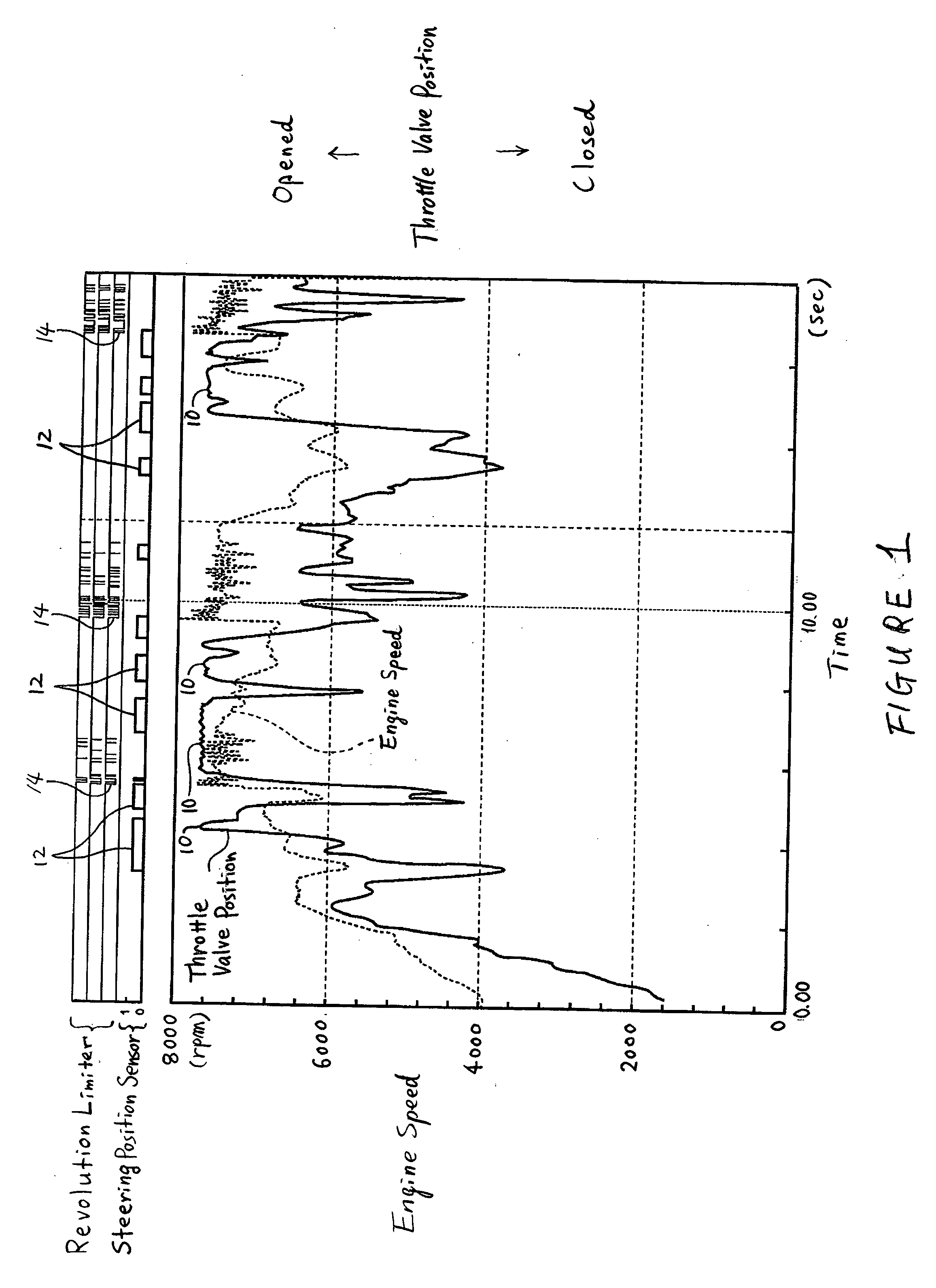
[0009] One aspect of the present invention involves the recognition that when a rider sharply steers a personal watercraft the dynamic pressure within the jet pump often significantly decreases. The load on the engine consequently falls, potentially causing the engine to over-rev. In some arrangements, the engine can be provided with a revolution limiter that inhibits the engine from over-rewing.
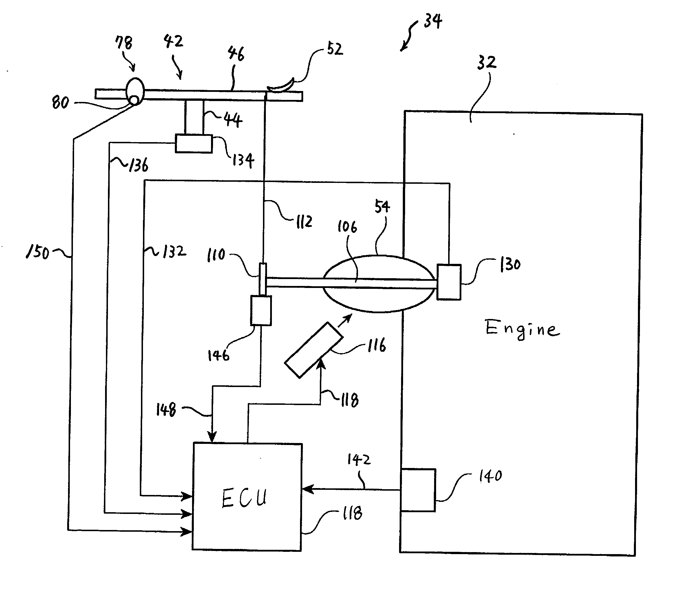
[0011] Consequently a further aspect of the present invention involves an improved engine control system for a watercraft that can inhibit an engine from over-revving even when the watercraft is turned sharply at a relatively high rate of speed. The watercraft comprises an internal combustion engine that powers the propulsion device. A control device is configured to control a magnitude of engine power of the engine. A steering mechanism is arranged to steer a thrust direction of the propulsion device. First sensing means are provided for sensing the magnitude of engine power or a magnitude of engine load. Second sensing means are provided for sensing an angular position of the steering mechanism. The control device decreases the magnitude of engine power when the control device determines that the magnitude of engine power is greater than a preset magnitude of engine power or the magnitude of engine load is greater than a preset magnitude of engine load based upon an output from the first sensing means and that the angular position of the steering mechanism is greater than a preset angular position based upon an output from the second sensing means.

Problems solved by technology

The load on the engine consequently falls, potentially causing the engine to over-rev.

Method used


Image

  • Engine control system for watercraft
  • Engine control system for watercraft
  • Engine control system for watercraft

Examples


Embodiment Construction

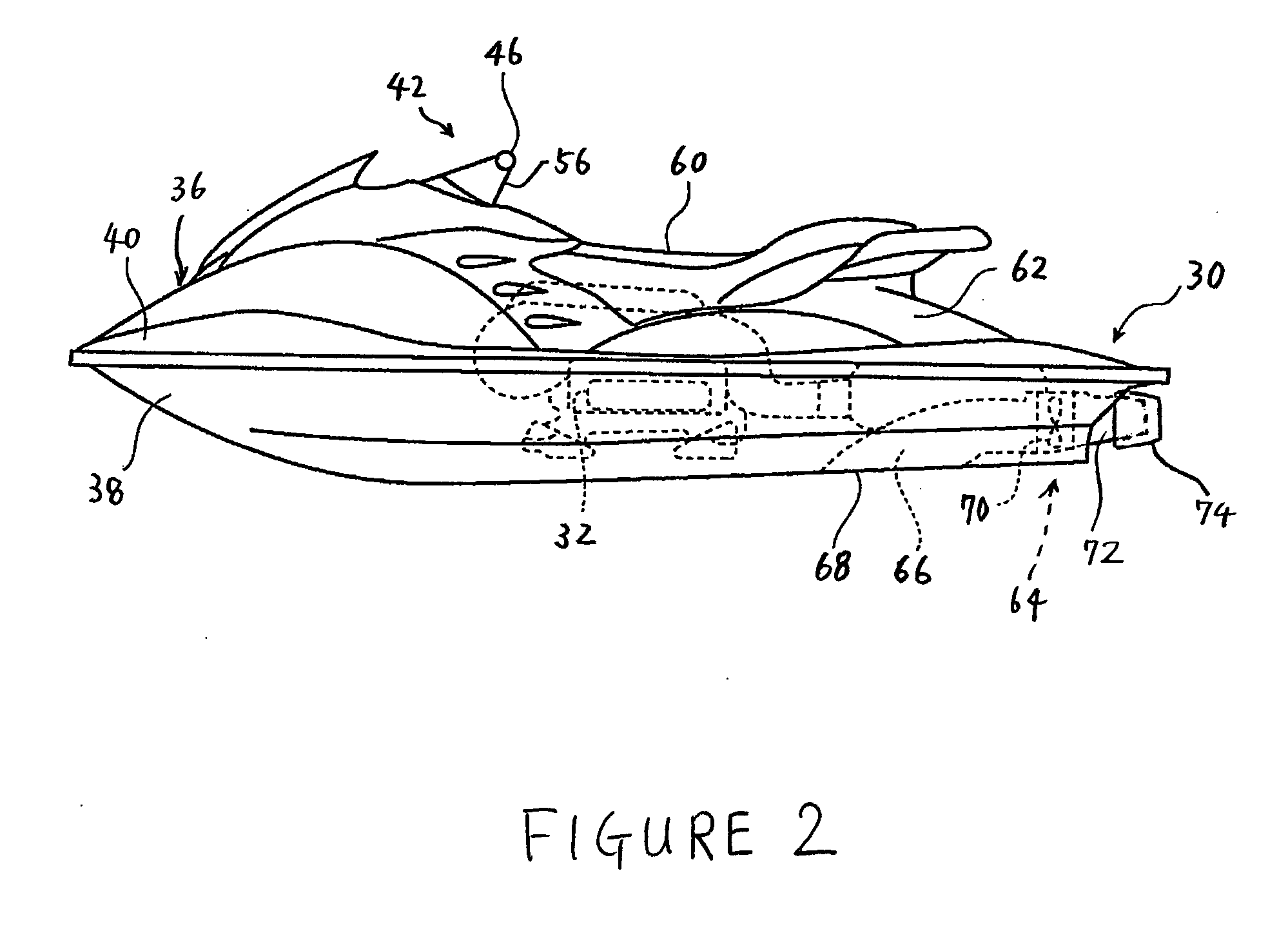
[0036] With initial reference to FIGS. 2-6, an overall construction of a personal watercraft 30 is described. The watercraft 30 incorporates an internal combustion engine 32 controlled by an engine control system 34 (FIG. 7) that is configured and operated in accordance with a preferred embodiment of the present invention. This engine control system 34 has particular utility with a personal watercraft, and thus is described in the context of the personal watercraft. The control system, however, can be applied to other types of watercraft as well, such as, for example, small jet boats.

[0037] The personal watercraft 30 preferably comprises a hull 36 generally formed with a lower hull section 38 and an upper hull section or deck 40. The lower hull section 38 can include one or more inner liner sections to strengthen the hull 36 or to provide mounting platforms for various internal components of the watercraft 30. Both the hull sections 38, 40 preferably are made of, for example, a mold...


PUM


Abstract

A personal watercraft has a jet pump propulsion device. An engine powers the propulsion device and a control device controls engine speed. A steering mechanism steers a thrust direction of the propulsion device. An engine load sensor or an engine speed sensor senses an engine load or an engine speed, respectively. A steering position sensor senses an angular position of the steering mechanism. The control device decreases engine speed when the engine load or the engine speed is greater than a preset engine load or the engine speed, respectively, and the angular position of the steering mechanism is greater than a preset angular position.

Description

PRIORITY INFORMATION[0001] This application is based on and claims priority under 35 U.S.C. .sctn.119 to Japanese Patent Applications No. 2002-211503, filed on Jul. 19, 2002, and No. 2003164792, filed on Jun. 10, 2003, the entire contents of which are hereby expressly incorporated by reference herein.BACKGROUND OF THE INVENTION[0002] 1. Field of the Invention[0003] The present invention generally relates to an engine control system for a watercraft, and more particularly relates to an improved engine control system for a watercraft that controls an engine in accordance with a state of a steering mechanism of the watercraft.[0004] 2. Description of Related Art[0005] Personal watercraft has become popular in recent years. This type of watercraft is quite sporting in nature and carries one or more riders. A hull of the personal watercraft commonly defines a rider's area above an engine compartment. An internal combustion engine powers a jet pump unit that propels the watercraft by disc...

Claims


Application Information

Patent Timeline
Patent Type & Authority Applications(United States)
IPC IPC(8): B63H11/08B63B35/73B63H21/21B63H21/22F02D29/02F02D45/00
CPCB63H21/213
Inventor KINOSHITA, YOSHIMASAITO, KAZUMASA
Owner YAMAHA MARINE KK
Learn More