
Semiconductor device and manufacturing method thereof, electro optic device, liquid crystal display device, electronics device

Active Publication Date: 2004-04-29
SAMSUNG ELECTRONICS CO LTD
View PDF9 Cites 22 Cited by
  • Summary
  • Abstract
  • Description
  • Claims
  • Application Information

AI Technical Summary

Benefits of technology

[0010] Moreover, another object of the present invention is to enable the manufacture of a large size semiconductor device while employing a small size second substrate in order to facilitate the handling during the positioning or manufacture of the element chip and second substrate upon providing a semiconductor device and electro-optic device utilizing this technology.

Problems solved by technology

Nevertheless, a sophisticated and complex manufacturing process is required for creating a function element of a desired performance.
When manufacturing the likes of a display panel, since the support substrate, function element, wiring and so on are formed in a series of processes, a complex manufacturing process is inevitable, and, generally speaking, the manufacturing cost tends to be costly.
Nevertheless, when employing a large size substrate as the subject to be transcribed, it is unexpectedly difficult to accurately position the element chip, which is the transcriptional target, and such substrate.
In particular, with a print substrate or flexible print circuit, the expansion and contraction of the substrate is considerable.
Further, when the substrate of the subject to be transcribed becomes a large size, it becomes necessary to enlarge the related manufacturing device.
When the substrate becomes a large size, handling during the manufacture also becomes difficult.

Method used


Image

  • Semiconductor device and manufacturing method thereof, electro optic device, liquid crystal display device, electronics device
  • Semiconductor device and manufacturing method thereof, electro optic device, liquid crystal display device, electronics device
  • Semiconductor device and manufacturing method thereof, electro optic device, liquid crystal display device, electronics device

Examples


Embodiment Construction

in Electro-Optic Devices and Electronics Devices

[0166] FIG. 19 shows an example of the circuit connection of the display device having the structure of the invention described above. The display device 80 of the present embodiment comprises a light emitting layer OLED capable of emitting light by the electroluminescence effect at the respective pixel areas, and a retention volume C for storing the current for driving such light emitting layer OLED, and is structured by further comprising the thin film transistors T1 and T2 manufactured with the manufacturing method of the present invention. A selection signal line Vsel is supplied from the driver area 81 to the respective pixel areas. A signal line Vsig and a power source line Vdd are supplied from the driver area 82 to the respective pixel areas. As a result of controlling the selection signal line Vsel and signal line Vsig, the electric current program is performed to the respective pixel areas, and the luminescence of the light e...


PUM


Abstract

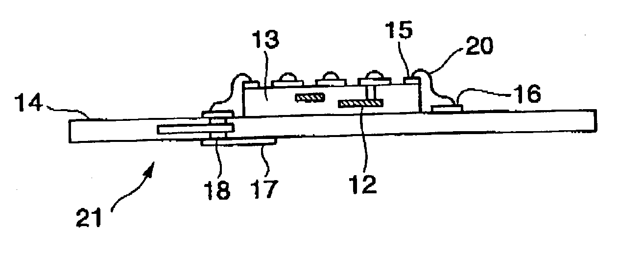
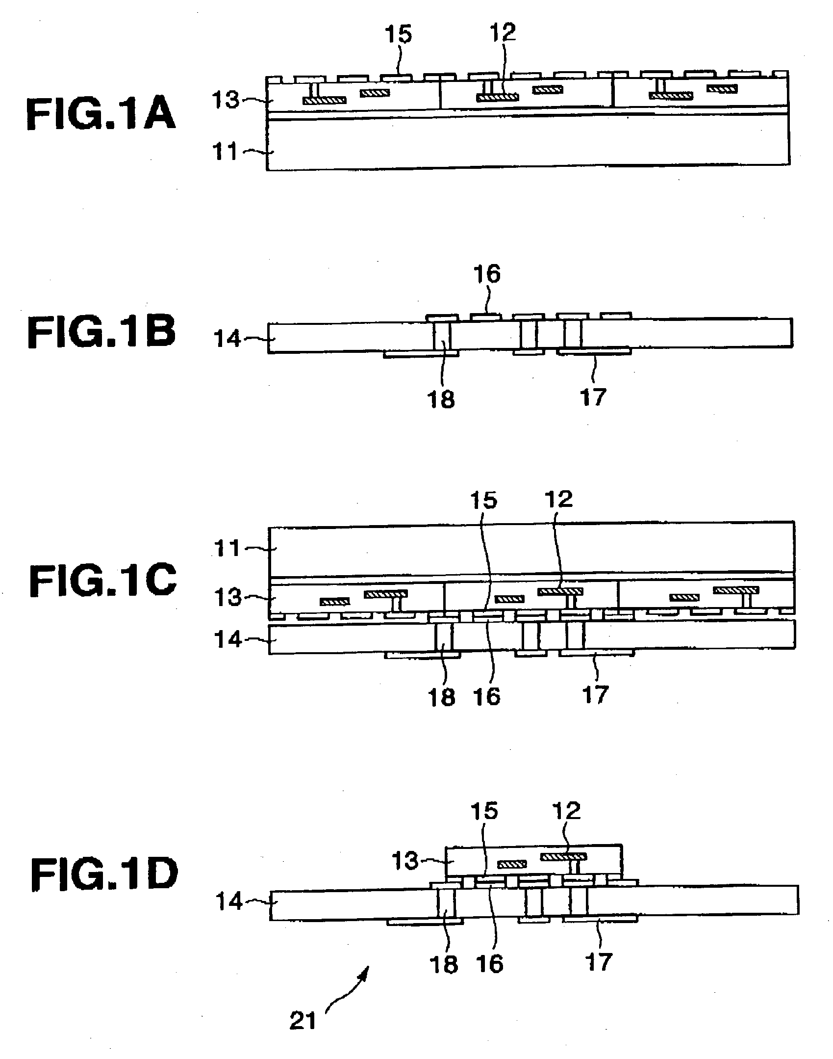
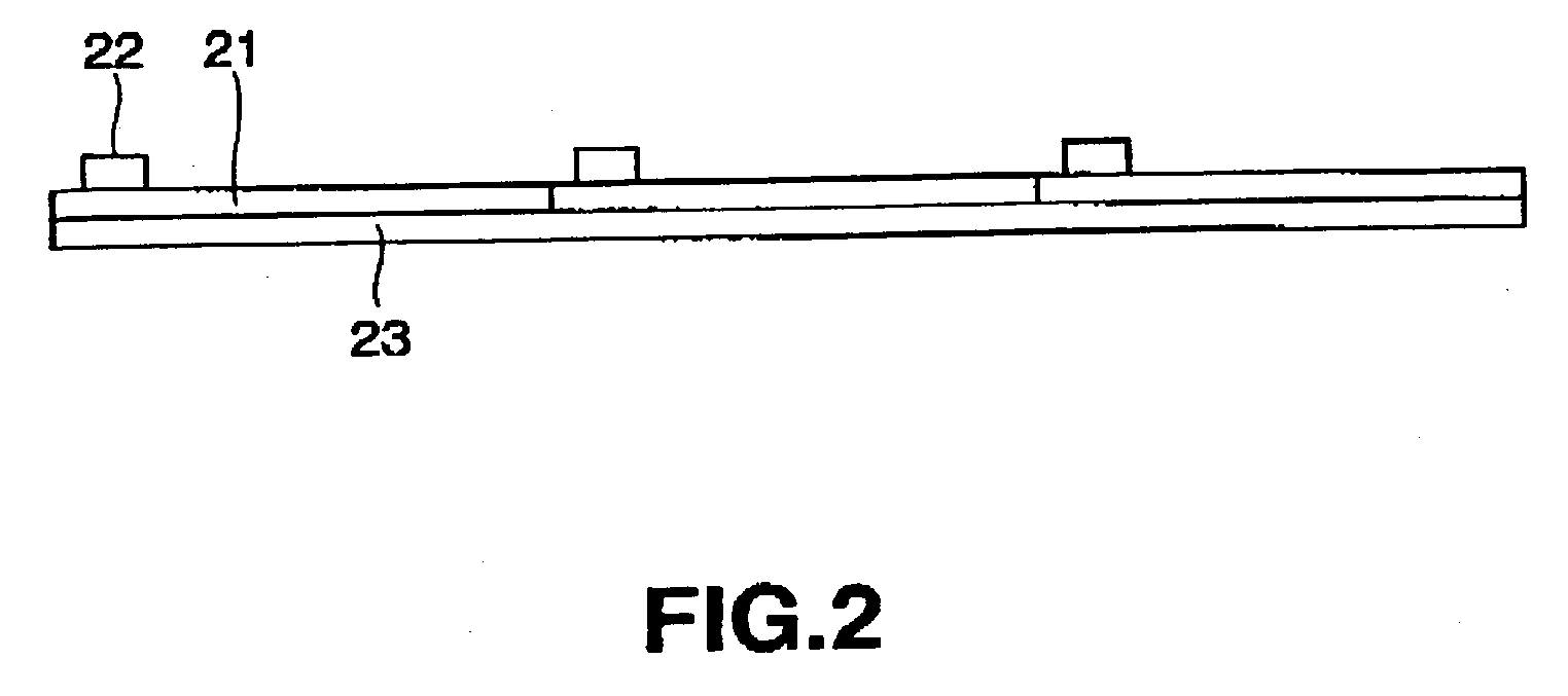
The present invention aims to manufacture a large size semiconductor device with the inter-substrate transcription technology of thin film circuits. Enlargement is enabled by disposing a plurality of second substrates (21) in a tile shape. As the second substrate (21), a print substrate or flexible print circuit having double-sided wiring or multilayer wiring is employed. The plurality of second substrates (21) is driven independently, and the plurality of second substrates (21) is made to mutually overlap, and a drive circuit (23) is disposed at such overlapping portion. Moreover, the plurality of second substrates (21) is made to mutually overlap, and the mutual circuits are connected at such overlapping portion.

Description

[0001] 1. Field of the Invention[0002] The present invention pertains to a semiconductor device and electro-optic device employing stripping-transcription technology for stripping the thin film chip formed on a substrate and, by transcribing this to another substrate, assembling a semiconductor device. The present invention also relates to the manufacturing method of such semiconductor device and electro-optic device.[0003] 2. Description of the Related Art[0004] A semiconductor device, for example, an electro-optic device such as a liquid crystal display device or organic EL display device, comprises function elements for carrying out a certain function of the likes of a thin film transistor or organic electroluminescence (EL) element, and a display panel including the wiring and support substrate between such function elements. Here, an electro-optic device shall mean general devices comprising an electric-optic element that emit light by an electrical effect, or which changes the...

Claims


Application Information

Patent Timeline
IPC IPC(8): G02F1/1347G02F1/1343H01L21/20H01L21/336H01L21/68H01L21/77H01L21/84H01L27/32H01L29/786H01L51/56H05B33/10
CPCG02F2001/13613H01L27/1288H01L27/1214H01L27/3255H01L27/3293H01L51/56H01L2221/68354H01L2221/68359H01L2221/68363H01L2221/68368H01L2224/16225H01L2224/48091H01L2224/48227H01L2227/326H01L2924/01079H01L2924/30105H01L21/6835H01L2924/00014H01L2924/12044H01L2224/48465H01L27/1259G02F1/13613H10K59/129H10K59/18H10K71/80H10K59/1201H10K71/421H10K71/135H01L2924/00H05K3/46H10K71/00
Inventor KIMURA, MUTSUMIINOUE, SATOSHIUTSUNOMIYA, SUMIOHARA, HIROYUKIMIYAZAWA, WAKAO
Owner SAMSUNG ELECTRONICS CO LTD
Learn More