Method and apparatus for adjusting the contents of a needle-less injector

a needle-less injector and contents technology, which is applied in the field of needle-less injector contents adjustment methods and apparatuses, can solve the problems of pain for patients, high production costs of traditional needle injectors, hypodermic syringes, etc., and achieves the effect of easy use with pre-packaged medication doses, easy use, and convenient us

Inactive Publication Date: 2004-05-06
WISE ROGER R +1
View PDF1 Cites 25 Cited by
  • Summary
  • Abstract
  • Description
  • Claims
  • Application Information

AI Technical Summary

Benefits of technology

[0011] A needle-less injector may include an adjustment switch in mechanical contact with a driver. The adjustment switch may be configured such that one can displace the switch to expel air or gas contained in the needle-less injector prior to administration of a needle-less injection. The adjustment switch may include a portion that is disposed within an adjustment slot configured in the housing of a needle-less injector. The adjustment switch may be moved along the adjustment slot to correspondingly displace the driver of the needle-less injector toward the dispensing end thereof. This displacement of the driver may expel air or gas from that portion of the needle-less injector that contains the injectable product. Alternatively or additionally, displacement of the driver may expel at least a portion of the injectable product from the needle-less injector. This may be particularly advantageous when one wishes to reduce the volume of the injectable product that will be injected with the needle-less injector.
[0028] As depicted in FIG. 3, the adjustment switch 106 is preferably of a suitable configuration to accommodate a user's finger (herein used to include the thumb), and may further include a non-slip surface 301 to aid in maintaining the interaction between a user's finger and the switch. This may be especially useful in those embodiments where a substantial amount of force is required to displace the adjustment switch 106. Furthermore, the adjustment switch 106 is preferably of a suitable size and shape to entirely cover the adjustment slot 112 before, during and after displacement of the switch. This may aid in maintaining the sterility of the adjustment slot 112 and the interior of the needle-less injector 100, since covering the adjustment slot 112 may prevent particles from clogging or otherwise blocking the movement of the adjustment switch 106.
[0030] In those embodiments wherein the adjustment switch 106 partially or entirely wraps around the exterior of the needle-less injector 100, the adjustment switch 106 may include multiple transecting members 109, as described below. Including multiple transecting members 109 may provide additional stability to a clamp (FIG. 4) or sleeve (FIG. 5) adjustment switch 106 as a user displaces the same to adjust the contents of the product section 102 of a needle-less injector 100, and may reduce or eliminate the friction between the adjustment switch 106 and the exterior of the housing 101. Moreover, the inclusion of multiple transecting members 109 may partially or entirely alleviate the creation of torsional force caused by displacement of the adjustment switch 106. In those embodiments wherein one transecting member 109 is included, or wherein a number of transecting members 109 are included but are unevenly configured about the axis of the driver 104, axial movement of the adjustment switch 106 may result in a torque being created that hampers the forward movement of the driver 104 and / or necessitates a greater amount of force from a user to move the adjustment switch 106.
[0032] In those embodiments wherein the adjustment switch 106 is a sleeve adjustment switch, the friction between the adjustment switch 106 and the housing 101 may be eliminated, since the interior diameter of the sleeve adjustment switch 106 may be greater than the exterior diameter of the needle-less injector housing 101. Therefore, the adjustment switch 106 may be displaced without contacting the housing 101; thereby obviating the need to overcome resistance to movement owing to friction between the sleeve adjustment switch 106 and the housing 101 of the needle-less injector 100.
[0034] The adjustment switch 106 may further include a transecting member 109 to provide mechanical contact between the adjustment switch 106 and the driver 104. In preferred embodiments of the present invention, the transecting member 109 is only in contact with the driver 104 on its side 110, and not on its end 111 (FIG. 6). A space 601 is preferably included between the end 111 of the transecting member 109 and the member receiving indentation 602. This may allow the driver 104 to glide by the transecting member 109 during the administration of a needle-less injection.
[0045] A complete "injection length" is the entire distance that a driver 104 may be displaced during the administration of a needle-less injection. By configuring the adjustment slot 112 at this length, a user may adjust the contents of the product section 102, by: (1) expelling air or gas 201 that develops in the product section 102; (2) reducing the volume of injectable product 202 contained in the product section 102 (e.g., reducing the dosage of a pre-filled needle-less injector 100); or (3) a combination thereof. In those instances where a user may utilize the adjustment switch 106 to adjust the volume of the injectable product 202, it may be desirable for the adjustment slot 106 to include semi-cylindrical slots 803 (FIG. 8b), or for the housing 101 to include graduations 804 indicative of the volume of the product section 102 (FIG. 8c). A user may then displace the adjustment switch 106 to reach a desired volume of injection, by visually referring to the graduations 804 on the housing 101.

Problems solved by technology

In addition, the traditional method of intradermal injections requires actual physical contact and penetration of a needle through the skin surface of the patient, which can be painful for the patient.
Traditional needle injectors, such as hypodermic syringes, are also expensive to produce and difficult to use with prepackaged medication doses.
Needle injectors also suffer from increased danger of contamination exposure to health care workers administering the injections, and to the general public when such injectors are not properly disposed of.
Needle-less injectors are designed to obviate some or all of the aforementioned limitations associated with hypodermic needle syringes; although in overcoming such limitations, needle-less injectors present difficulties of their own.
One such difficulty is the removal of air or gas from that portion of a needle-less injector that contains the injectable product (e.g., a pharmaceutical solution), especially when the amount of air or gas contained in that portion is or becomes substantial.
Regardless of the mechanism responsible for the presence of air or gas in a needle-less injector, subdermal hematomas, tissue damage, and scarring from mechanical force injury may result when pockets of such air or gas are present in an injector prior to dispensing the injectable product contained therein.
Thus, air or gas pockets accelerated against the skin lead to the formation of a bruise and can be quite painful for the recipient, whereas liquid medication passes into and / or through the skin without discomfort.
Furthermore, when a cap is removed from the end of a pre-filled needle-less injector, exposing the dispensing area for application to the skin surface, any air or gas pocket not already situated at the dispensing end may tend to migrate toward that end, due to the pressure change caused by cap removal.
This motion of the air or gas pocket may force some of the injectable product from the needle-less injector, thereby diminishing the volume of the product that will be injected into the recipient.
This may render the dosage level inaccurate, if a nontrivial volume of the product is lost from the injector prior to use.
In the context of injection by more traditional means such as with a preloaded syringe, it is well established that any significant amount of air or gas in such a device will cause pain for the recipient and potentially far more dire consequences if the amount of air is substantial.
However, those administering traditional injections can readily obviate these limitations by evacuating air from the liquid-containing chamber of a syringe by partially depressing the plunger while the syringe is inverted immediately prior to administration of an injection.
This is generally not possible with conventional needle-less injectors, as the entire volume of a needle-less injector ampoule is generally evacuated in one step during normal operation.
This fixed attribute of conventional needle-less injectors presents difficulty to those for whom the volume of a pre-filled needle-less injector does not correlate with their physiological or therapeutic needs.
This problem generally manifests in one of two types of injection recipient, although the need to adjust the volume of a needle-less injection is by no means limited to these scenarios: (1) injection recipients for whom the pre-filled volume of a needle-less injection is too large, and (2) injection recipients for whom the volume of required injections varies over a period of time.

Method used


Image

  • Method and apparatus for adjusting the contents of a needle-less injector
  • Method and apparatus for adjusting the contents of a needle-less injector
  • Method and apparatus for adjusting the contents of a needle-less injector

Examples


Embodiment Construction

Adjusting the Contents of a Needle-Less Injector

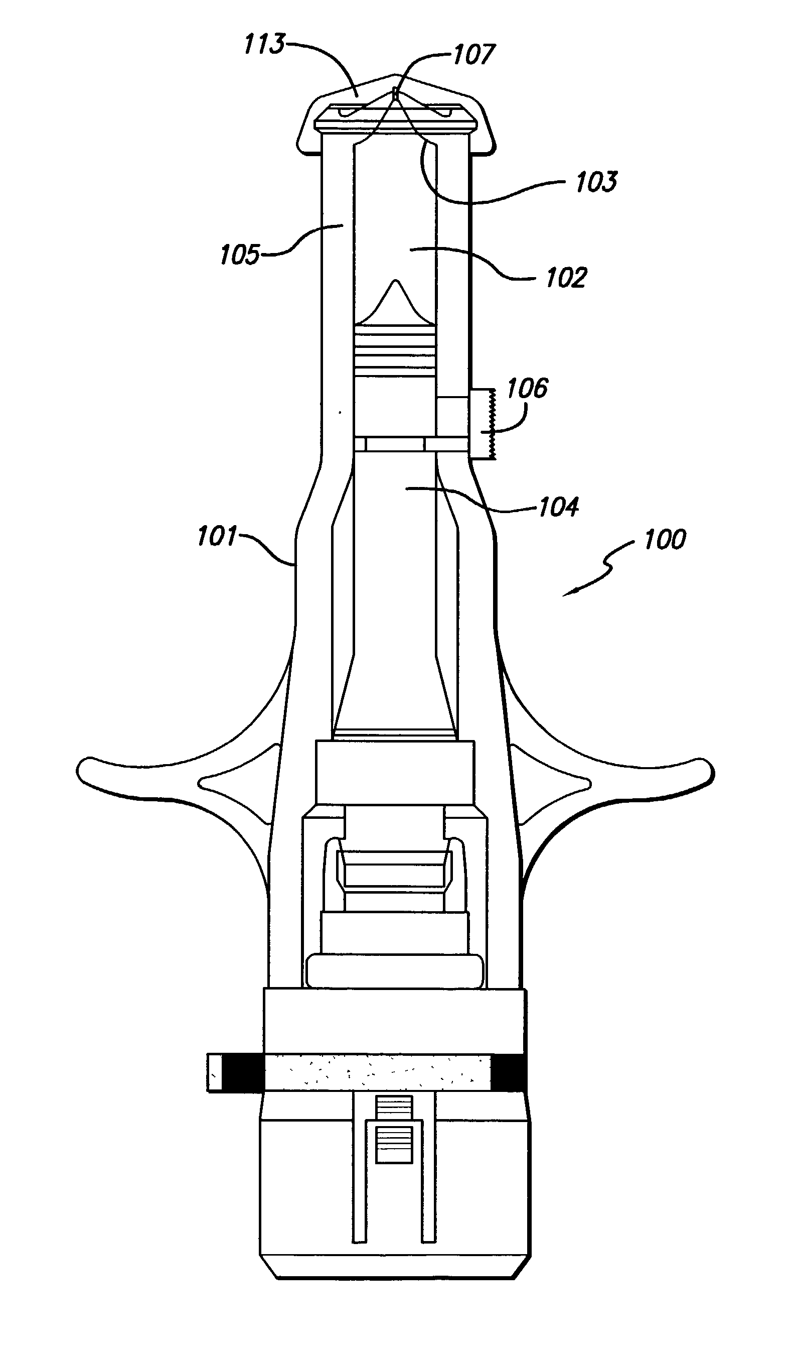
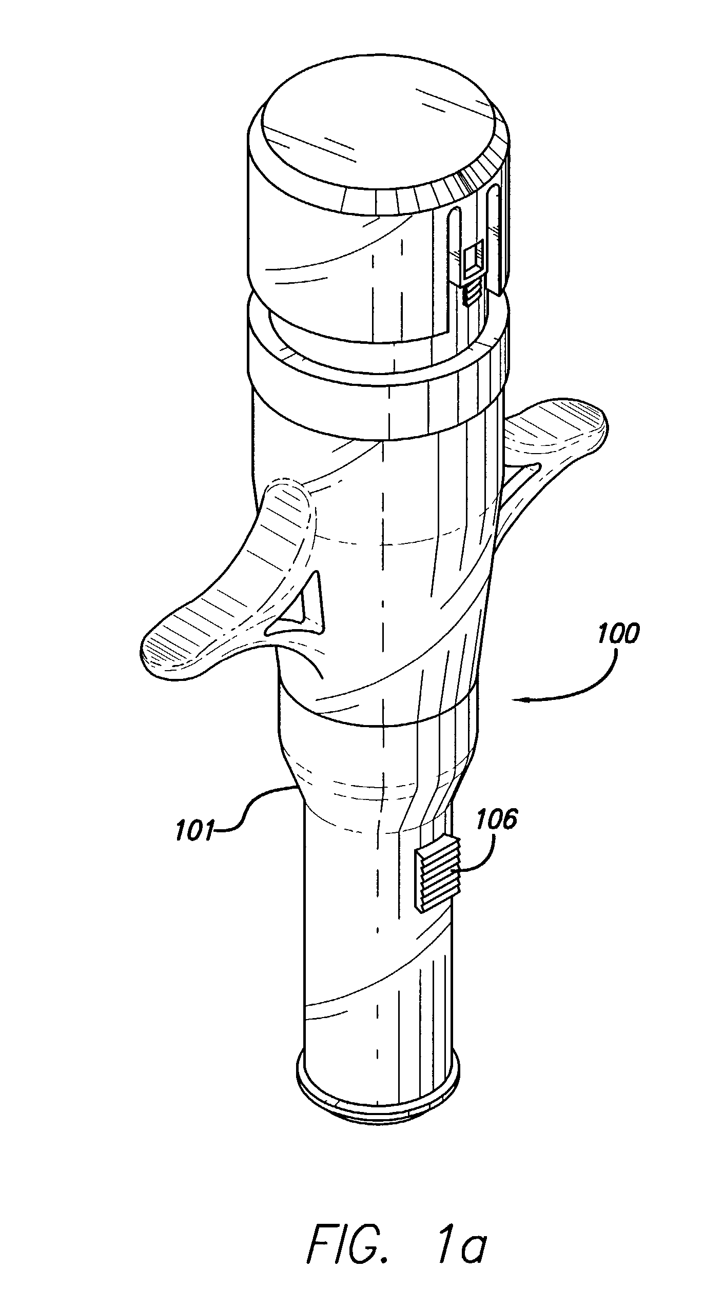
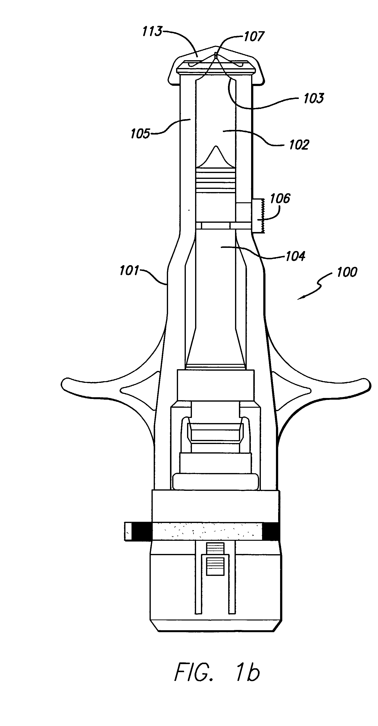
[0049] A needle-less injector contains an injectable product, and an air bubble has developed in the product section thereof. A sleeve adjustment switch is included on the needle-less injector. A user removes a cap from the dispensing end of the needle-less injector, and, holding the needle-less injector with the dispensing end oriented in an "up" direction, the user displaces the sleeve adjustment switch until the air bubble is evacuated from the product section of the needle-less injector and a small volume of fluid begins being forced through the orifice of the needle-less injector. The user then ceases displacement of the adjustment sleeve, and administers a needle-less injection with the needle-less injector.

[0050] While the description above refers to particular embodiments of the present invention, it should be readily apparent to people of ordinary skill in the art that a number of modifications may be made without departing fr...


PUM


Abstract

A method and apparatus for adjusting the contents of a needle-less injector that contains an injectable product are described. A needle-less injector includes an adjustment switch in mechanical contact with the driver of a needle-less injector. A user may displace the adjustment switch to expel air or gas contained in the product section of the needle-less injector prior to administration of a needle-less injection with the same. The adjustment switch may alternatively or additionally be used to expel at least a portion of the injectable product contained in the needle-less injector to reduce the volume of the product to be injected with the needle-less injector.

Description

[0001] This invention relates to needle-less injectors, and in particular, to methods and devices for adjusting the contents of a needle-less injector once the same is filled with an injectable product, prior to the administration of an injection.[0002] Traditionally, fluids such as medications are injected into patients, either subdermally or intradermally, using hypodermic syringe needles. The body of the syringe is filled with the injectable fluid and, once the needle has pierced the patient's skin, the syringe plunger is depressed so as to expel the injectable fluid out of an opening in the needle. The person performing the injection is usually a trained medical services provider, who manually inserts the hypodermic needle between the layers of a patient's skin for an intradermal injection, or beneath the skin layers for a subcutaneous injection.[0003] Intradermal or subdermal delivery of a medication through the use of a hypodermic needle requires some skill and training for pr...

Claims


Application Information

Patent Timeline
Patent Type & Authority Applications(United States)
IPC IPC(8): A61M5/30A61M5/315
CPCA61M5/30A61M2205/6063A61M5/3156
Inventor WISE, ROGER R.LEVY, SETH D.
Owner WISE ROGER R
Why Eureka
Try Eureka