Reverse osmosis liquid purification system and method

a liquid purification system and reverse osmosis technology, applied in the direction of moving filter element filters, filtration separation, separation processes, etc., can solve problems such as flow limiting factors

Inactive Publication Date: 2004-05-13
ORION TECH & COMMERCE
View PDF8 Cites 15 Cited by
  • Summary
  • Abstract
  • Description
  • Claims
  • Application Information

AI Technical Summary

Benefits of technology

0009] Another object of the present invention is to provide a system which compensates for flow limiting factors so that the permeate is produced at a constant flow rate.
0010] Another object of the present invention is to keep an inflow rate and outflow rate ratio constant around the membrane, such that permeate flow rates are kept constant.

Problems solved by technology

There are also other flow limiting factors.

Method used


Image

  • Reverse osmosis liquid purification system and method
  • Reverse osmosis liquid purification system and method

Examples


Embodiment Construction

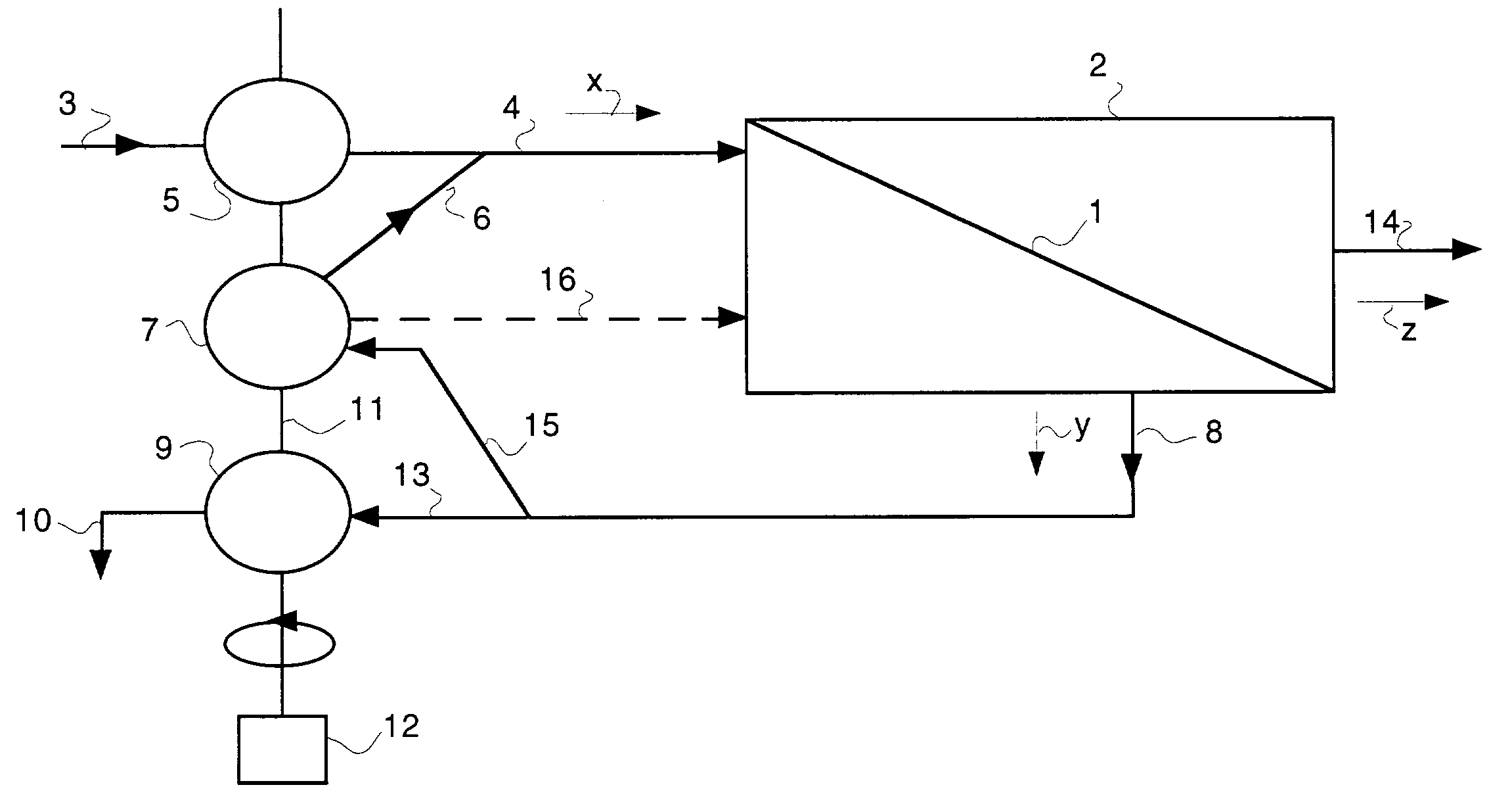
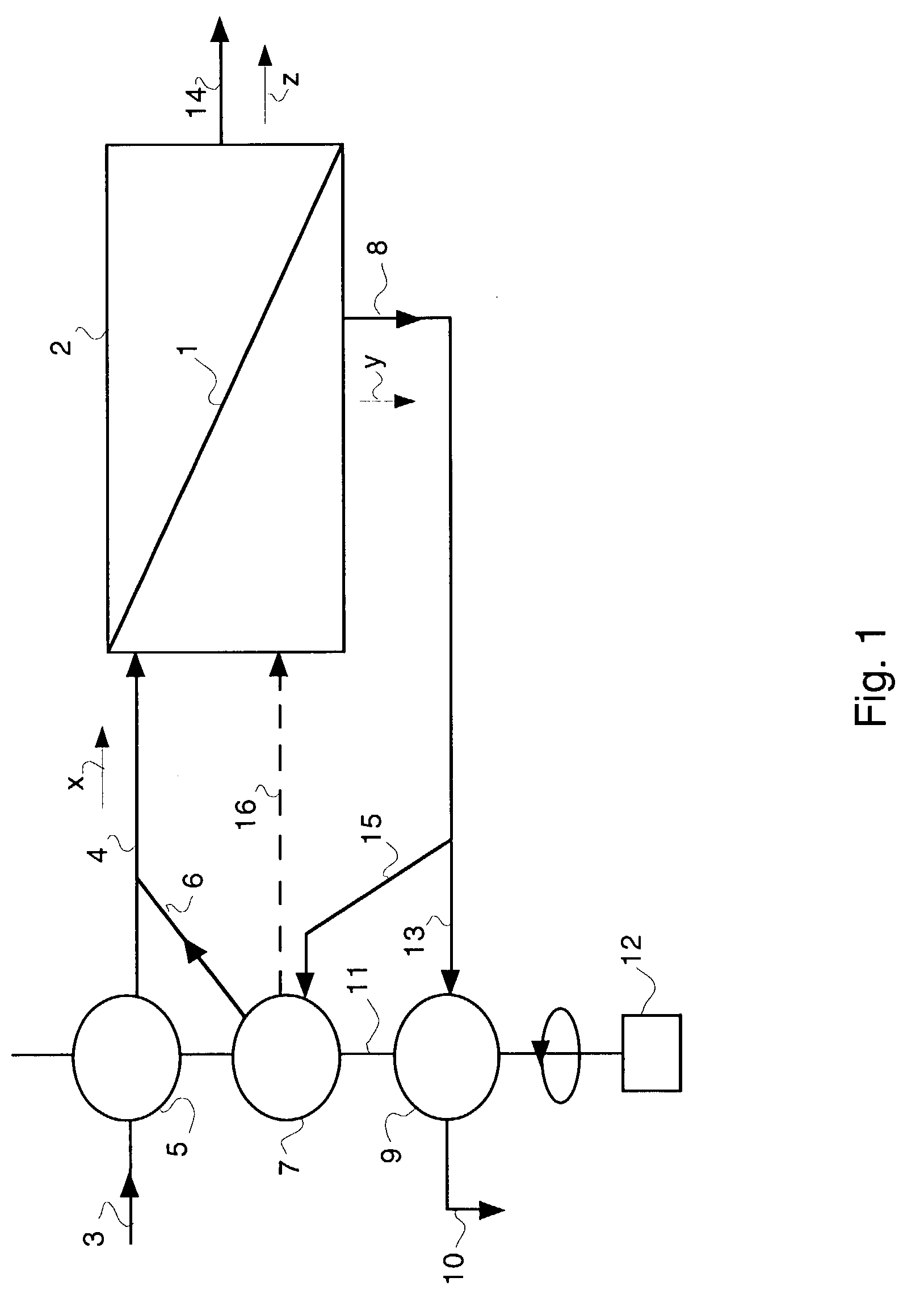
[0020] The purifier is to produce 6 liters of purified water (permeate) per minute. This requires a high rate membrane 1 with a surface area of about five square meters using reverse osmosis design criteria common in the art. If the purifier is to give a recovery rate of water of fifty percent, the feed water 4 flow rate (x), also called the rate of delivery (x), is provided at 12 liters per minute by the flow rate control means 5, such as the feed water delivery pump 5. In the simplest form of this invention, the outlet 8 water flow rate (y), also called the rate of removal (y), is provided at 6 liters per minute by the flow rate control means 9, such as the feed water removal pump 9, and no recirculation occurs through the conduit 15 and flow rate control means 7. Hence the discharge conduit 10 removes 6 liters per minute from the system. To conserve mass according to equation 1, the permeate flow rate (z) through the membrane 1 is held at 6 liters per minute.

[0021] A slightly mor...


PUM

PropertyMeasurementUnit
temperatureaaaaaaaaaa
concentrationaaaaaaaaaa
surface areaaaaaaaaaaa

Abstract

A water purification system and method based on reverse osmosis is provided. An inlet of supplied water to be purified is driven by a first flow propelling device which drives inlet supplied water flow to an upstream side of a membrane. An outlet of reject water from the upstream side of the membrane is driven by a second flow propelling device. The first and second flow propelling devices are powered by a common driving shaft or otherwise linked or controlled so that a ratio of inlet flow to outlet flow is maintained constant and a rate of permeate flow from a downstream side of the membrane is also kept constant.

Description

[0001] Purification of water by reverse osmosis generally involves forcing pressurized salt water, or water with other dissolved solids therein, through an osmotic membrane.[0002] Salt or other dissolved solid containing feed water is introduced by means of a high pressure pump to the upstream side of a permeable membrane. The desalted product, also called permeate, is removed from the downstream side of the membrane. It is a known fact that the permeate flow rate is much dependent upon the temperature of the water and the net driving pressure. All manufacturers' data are given for a reference temperature of 25.degree. C. Lowering of the temperature to about 10.degree. C. usually means that the permeate flow is halved.[0003] The driving pressure, strictly speaking the net driving pressure, is the difference between the system pressure and the osmotic pressure. The system pressure is the pressure across the membrane. The osmotic pressure is determined by and is a function of the conc...

Claims


Application Information

Patent Timeline
Patent Type & Authority Applications(United States)
IPC IPC(8): B01D61/02B01D61/12
CPCB01D61/12B01D61/025
Inventor BRANDT, HARRYNEMETH, TIBOR
Owner ORION TECH & COMMERCE
Why Eureka
Try Eureka