Microparticle arrangement film, electrical connection film, electrical connection structure, and microparticle arrangement method

a technology of microparticles and adhesives, applied in the direction of coupling device connections, sustainable manufacturing/processing, final product manufacturing, etc., can solve the problems of poor dispersing efficiency, leakage at neighbor electrodes, and difficulty in uniformly pouring sealing resin in a short tim

Inactive Publication Date: 2004-06-03
SUZUKI TATSUO +2
View PDF0 Cites 64 Cited by
  • Summary
  • Abstract
  • Description
  • Claims
  • Application Information

AI Technical Summary

Benefits of technology

0019] when the average particle diameter of the fine particles is 800 to 200 .mu.m, a degree of vacuum in the suction side is preferably -10 kPa or less,
0020] when the average particle diameter of the fine particles is 200 to 40 .mu.m, a degree of vacuum in the suction side is preferably -20 kPa or less, and
0021] when the average particle diameter of the fine particles is less than 40 .mu.m, a degree of vacuum in the suction side is preferably -30 kPa or less.

Problems solved by technology

However, these methods have inconveniences that a disposing efficiency is inferior, a process is troublesome, fine particles are placed more than necessarily, reversely fine particles are not disposed at requiring positions and so on.
In the case of connecting fine opposite electrodes, because of a problem such as a weak strength in individual connecting portions, it is generally necessary to seal the neighborhood therearound with a resin.
But the opposite fine electrodes have short distance at the connections, and so it is difficult to uniformly pour the sealing resin in a short time.
However, since the anisotropic conductive adhesive generally comprises the conductive fine particles dispersed at random in an insulating adhesive, the conductive fine particles are combined in a binder, or fine particles absent on the electrodes flow and are combined when heated and press-attached, whereby it is possibility to cause a leakage at neighbor electrodes.
In addition, even if fine particles are pressed on electrodes or bumps by heating and press-attaching, since a thin layer of an insulating material easily remains between the electrode and the fine particle, there occurs a problem of lowering a connecting reliability.

Method used


Image

  • Microparticle arrangement film, electrical connection film, electrical connection structure, and microparticle arrangement method
  • Microparticle arrangement film, electrical connection film, electrical connection structure, and microparticle arrangement method

Examples


example 2

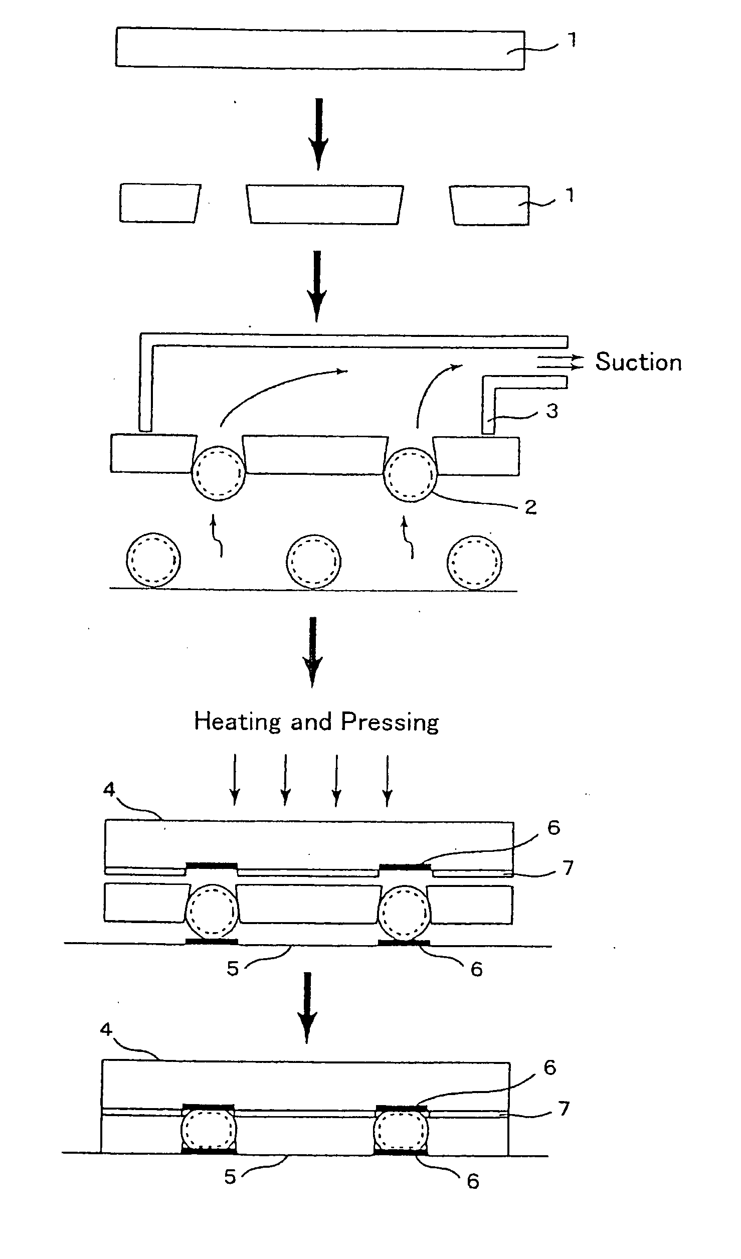
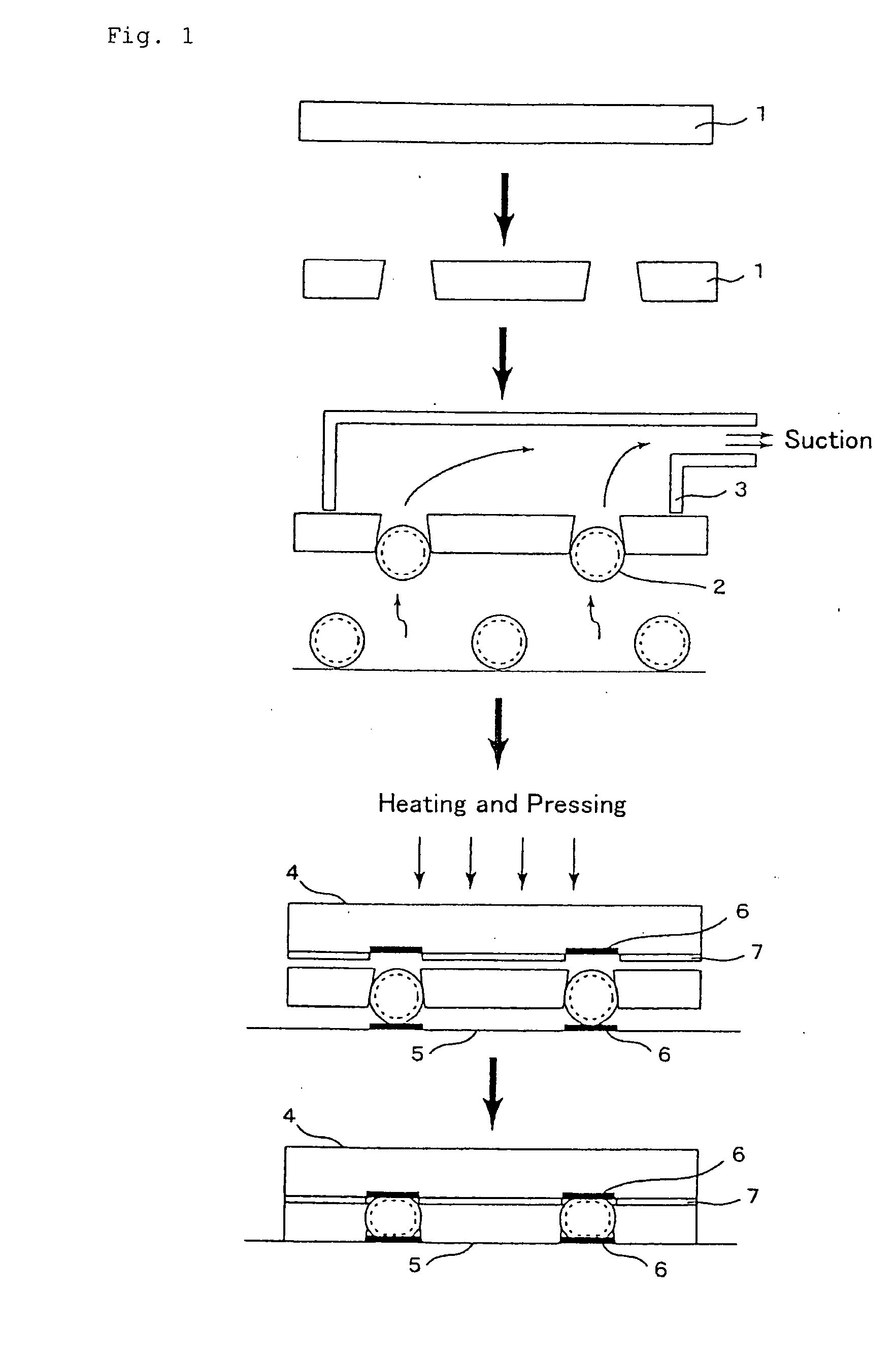
[0104] Fine particles of polystyrene of average diameter: 250 .mu.m, aspect ratio: 1.15 and CV value: 4% were prepared. Further, the polyimide film of Young's modulus: 6 GPa, thickness: 180 .mu.m and size: 2 cm.times.2 cm was formed with 32 holes to be square shaped at 0.5 mm pitch via the CO.sub.2 laser, such that the holes of CV value: 6% and aspect ratio: 1.25 would be shaped in taper of 220 .mu.m on the front side and 190 .mu.m on the back side of the film. By using the CO.sub.2 laser, the desired dimensions and shapes could be precisely formed. At the back side of the film, the suction openings of 7 mm diameter were attached such that all holes of film were covered and any leakage was not to be caused, and fine particles were sucked as the suction opening coming near to fine particles while sucked at the degree of vacuum of -30 kPa. Although particles of minute amount escaped to the vacuum side and particles of minute amount were adhered, they could be removed by as light air p...

example 3

[0106] Divinylbenzene based copolymer obtained by seed polymerization was classified by screening and a wet-classification into fine globes. Then, a nickel layer of 0.2 .mu.m thickness was formed onto the fine gloves by an electroless plating, and further a gold layer of 2.3 .mu.m thickness was formed by an electroplating. Particles thereof were further classified into metal-coated fine globes of average diameter: 75 .mu.m, aspect ratio: 1.03, CV value: 1%, K value: 4000 N / mm.sup.2, recover rate: 60%, coefficient of linear expansion at normal temperature: 50 ppm, and resistant value: 0.01 .OMEGA.. Further, the half-cured epoxy based film of Young's modulus: 0.4 GPa, thickness: 68 .mu.m and size: 1 cm.times.1 cm was formed via the CO.sub.2 laser with 18 holes in two rows of about 3 mm-separation at about 300 .mu.m pitches such that the holes would agree in position with the electrodes of IC chips, and formed via the CO.sub.2 laser to be CV value: 2% and aspect ratio: 1.04, and shaped...

example 4

[0111] On the fine globes of the methyl methacryl based cross-linking copolymer, the nickel layer of 0.1 .mu.m thickness was formed by an electroless plating, and further a gold layer of 0.9 .mu.m thickness was formed by an electroplating. Particles thereof were classified into metal-coated fine globes of average diameter: 45 .mu.m, aspect ratio: 1.05, CV value: 2%, K value: 2000 N / mm.sup.2, recover rate: 50%, coefficient of linear expansion at normal temperature: 80 ppm, and resistant value: 0.03 .OMEGA.. Further, the half-cured glass-epoxy based film of Young's modulus: 2 GPa, thickness: 60 .mu.m and size: 1 cm.times.1 cm was formed via the excimer laser with 16 holes in two rows of about 2 mm-separation at 150 .mu.m pitches, such that the holes would agree in position with the electrodes of IC chips, formed via the excimer laser to be CV value: 2% and aspect ratio: 1.05, and shaped in taper of 43 .mu.m on the front side and 38 .mu.m on the back side of the film. By using the exci...


PUM


Abstract

The present invention provides a method for disposing specific fine particles at arbitrary positions of a film with efficiency and ease, in just proportion and under a stable condition, and a fine particle-disposed film, that is to say, a method for disposing fine particles that basically disposes one particle in one hole, and fine particle-disposed film, as well as a conductively connecting film and a conductively connected structure, when opposite fine electrodes are connected, enabling to carry out easily an electric connection of high connecting reliability in a short time without causing leakage from neighbor electrodes by employing a film in which conductive fine particles are disposed at arbitrary positions thereof. The invention is a fine particle-disposed film, in which fine particles are disposed, the fine particles each having: an average particle diameter of 5 to 800 mum; an aspect ratio of less than 1.5; and CV value of 10% or less, wherein the film has holes at arbitrary positions in a surface thereof, the holes each having: an average hole diameter which is ½ to 2 times of the average particle diameter of the fine particle; the aspect ratio of less than 2; and the CV value of 20% or less, and the fine particles are disposed on the surface of the holes or inside the holes.

Description

[0001] The present invention relates to a fine particle-disposed film in which specific fine particles are disposed in the film, a conductively connecting film and a conductively connected structure, which are used to an electric connection between fine electrodes, and a method for disposing fine particles.PRIOR ART[0002] Conventionally, as methods of disposing fine particles at specific positions of a film, there have been used a method of mechanically placing individual particles on the film, a method of transferring previously disposed particles to the film, a method of coating an adhesive or the like at the specific positions of the film and scattering fine particles to adhere thereon, further a method of dispersing fine particles in a paste to coat them, and the others.[0003] However, these methods have inconveniences that a disposing efficiency is inferior, a process is troublesome, fine particles are placed more than necessarily, reversely fine particles are not disposed at r...

Claims


Application Information

Patent Timeline
Patent Type & Authority Applications(United States)
IPC IPC(8): B23K3/06H01L21/48H01L21/56H05K3/34
CPCB23K3/0607B23K3/0623H01L2924/07811H01L21/4853H01L21/563H01L2224/73203H01L2924/01046H01L2924/01078H01L2924/01079H05K3/3436H05K3/3478H05K2201/10378H05K2201/10424H05K2203/0113H05K2203/0338H05K2203/041H05K2203/082H01L2224/11015H01L2224/11013H01L2924/01019H01L2924/01087H01L2224/11334H01L2924/00H01L2224/05571H01L2224/05573Y02P70/50H01B5/16
Inventor SUZUKI, TATSUOFUKUOKA, MASATERUJUCHI, KENJI
Owner SUZUKI TATSUO
Why Eureka
Try Eureka