Three dimensional printing from two dimensional printing devices

Inactive Publication Date: 2004-06-17
CROM ELDEN WENDELL +1
View PDF3 Cites 118 Cited by
  • Summary
  • Abstract
  • Description
  • Claims
  • Application Information

AI Technical Summary

Benefits of technology

0017] 6.2 Using the methods of the present invention, successive cross-sectional areas of the desired Product will be printed using the Hardener as the ink on successive layers of the Substrate. Said layers of the Substrate will be stacked one on top of the other to form a Brick. Said Brick will be subjected to conditions that will cause said Hardener to take effect. Said conditions maybe one or more of aging, heating, electromagnet radiation, etc. Said Hardener of each layer, having been in contact with both the present layer and the subsequent layer will fuse said present layer to a portion of said subsequent layer. In the case where both cross-sectional areas have the Hardener placed on them in adjacent regions, the hardened regions of both will fuse. In the case where the present layer has been treated with said Hardener the corresponding area of the adjacent layer has not, preferably only a small portion of the said adjacent layer will harden. This pattern of hardened and unhardened regions is formed in the Brick. To improve the quality and strength of the Product, the Brick may be compressed in the direction of the layering; thereby increasing the transfer of a portion of the Hardener to the unprinted side of the Substrate thus increasing the bonding strength between the layers. A possible extension of this process would be to print both sides of the Substrate with the Hardener possibly combined with an additional binding agent. The Brick is then exposed to the Solvent to weaken and allow the unhardened portions of the Brick to be removed. What remains is the desired Product.
0018] 6.3 The primary intention of the present invention is to produce small volumes of arbitrarily shaped objects using readily available, inexpensive equipment. Thus reducing the cost of producing prototypes of and small production runs of the desired physical three-dimensional Product. While not exclusive to CAD/CAM, the primary benefit will be felt in those areas. In the future, a system

Problems solved by technology

Having specialized, unusual equipment, inherently makes that

Method used


Image

  • Three dimensional printing from two dimensional printing devices
  • Three dimensional printing from two dimensional printing devices

Examples


Example

[0023] 8.1 Preferred Embodiment

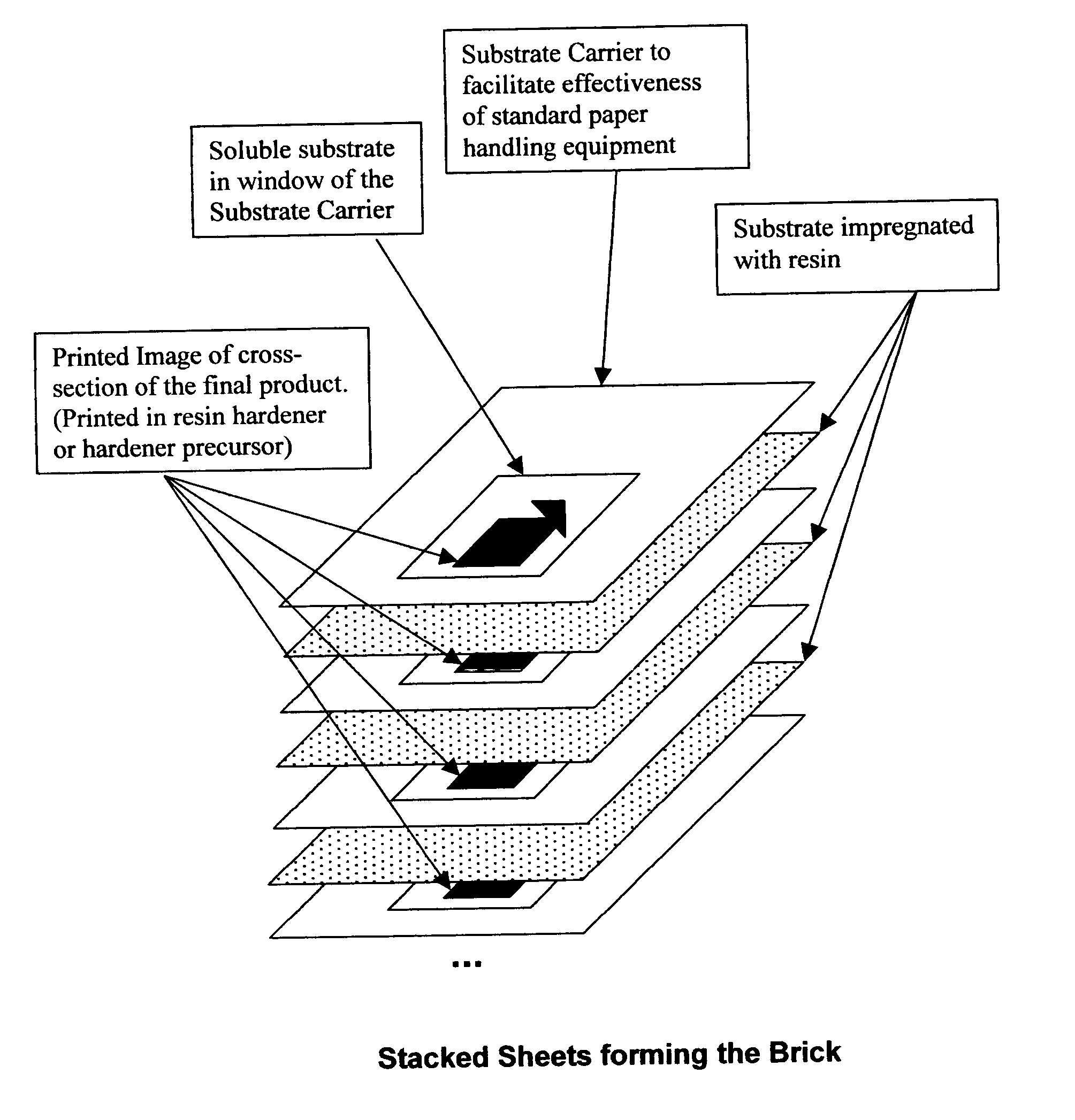
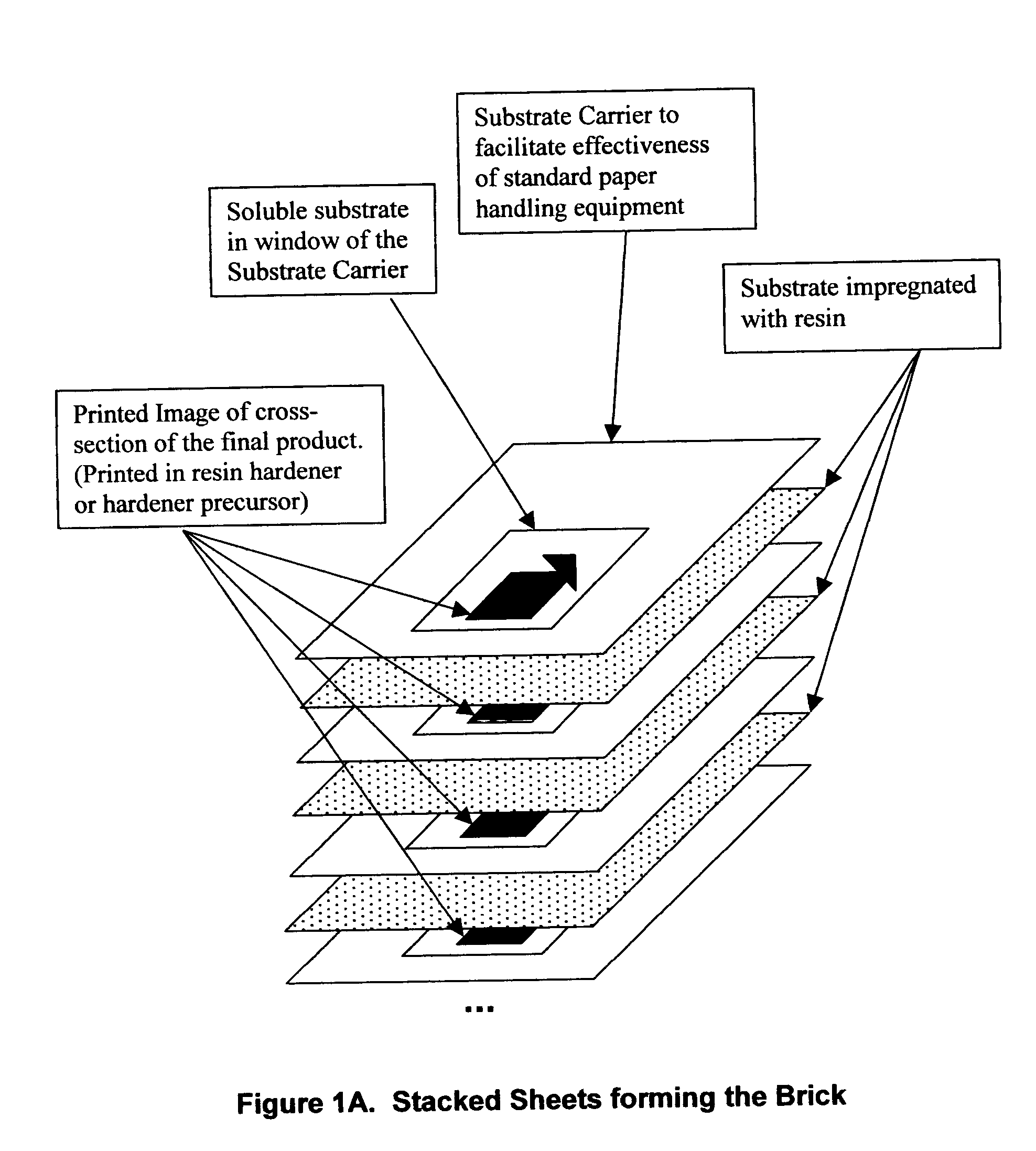
[0024] The simplest implementation of this method is to use an inkjet printer to apply resin-hardener to the areas intended to create the resultant Product to many separate sheets of water-soluble paper. Care must be taken to ensure that the resin will not significantly weaken the water-soluble paper. For the purposes of demonstration, Dissolvo.TM. D60S paper, Evercoat.TM. Fiberglass Resin and its hardener, and an HP.TM. 656cvr or Lexmark.TM. Z23le were chosen and used. The separate layers are subsequently stacked and other sheets of substrate that have been impregnated with fiberglass resin are inserted between each printed sheet. The resultant mass of paper, resin, and hardened resin, the Brick, contains the desired 3D Product. Said Brick is then submersed in water and then agitated by brushing, rubbing, and a mild pressure spray of solvent to erode the negative portions of the Brick, leaving behind the hardened resin in the shape of the desired Prod...


PUM

PropertyMeasurementUnit
Currentaaaaaaaaaa
Pressureaaaaaaaaaa
Coloraaaaaaaaaa

Abstract

A method of rapid prototyping a physical three-dimensional Product that can be preformed on readily available commercial 2D printing devices and paper handling equipment is presented. The method consists of using a 2D printing process to obtain a stack of sheets, each sheet printed with successive cross sectional areas of the desired product with ink (Hardener) that causes the sheet to become resistant to subsequent weakening and removal after the creation of the Brick. The Brick, containing both the positive (printed areas) and negative (unprinted areas), is then subjected to an agent(s) that weakens and removes the unwanted negative regions leaving only the desired Product.

Description

2.0 CROSS-REFERENCE TO RELATED APPLICATIONS[0001] This application is based upon provisional application for patent number 60 / 418,297 filed on Oct. 15, 2002.3.0 STATEMENT REGARDING FEDERALLY SPONSORED RESEARCH OR DEVELOPMENT[0002] Not Applicable4.0 SEQUENCE LISTING OR PROGRAM[0003] Not Applicable5.0 BACKGROUND OF THE INVENTION[0004] 5.1 With the advent of modem computers and sophisticated CAD (Computer Aided Design) systems, many methods of CAM (Computer Automated Manufacturing) have been developed to provide both useable products and visual aids. Holding a physical model in one's hands often assists in finding defects and inspires design improvements. For architectural purposes, seeing the resultant building or landscape can go a long way toward bringing the project to life. For the movie and theater industries this methodology offers a new option for the creation of sets and props. For dentistry, creating a mold of what shape the teeth or jaw will become is crucial for successful ...

Claims


Application Information

Patent Timeline
IPC IPC(8): B29C67/00
CPCB29C67/0074B29C64/141B29C64/147B29C67/00
Inventor CROM, ELDEN WENDELLCROM, STACEY LYNN
Owner CROM ELDEN WENDELL
Why Eureka
Try Eureka