Membrane syringe

a membrane and syringe technology, applied in the field of syringes, can solve the problems of high cost, high cost, and high cost of the membrane, and achieve the effects of reducing the cost of manufacturing, and increasing the cost of manufacturing

Inactive Publication Date: 2004-06-17
TRANSCOJECT
View PDF12 Cites 35 Cited by
  • Summary
  • Abstract
  • Description
  • Claims
  • Application Information

AI Technical Summary

Problems solved by technology

The embodiment form described here however is extremely complicated in its construction since apart from the syringe cylinder three or four further components are required.
Disregarding the fact that this solution is also complicated in its design due to the multitude of components, the design of the membrane is very difficult with regard to manufacturing technology and is thus expensive.
The closure element to be placed onto the syringe connection likewise consists of a multitude of components and requires a costly manufacture and is thus expensive.

Method used


Image

  • Membrane syringe
  • Membrane syringe
  • Membrane syringe

Examples


Embodiment Construction

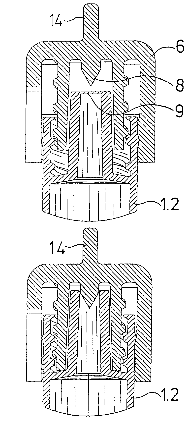
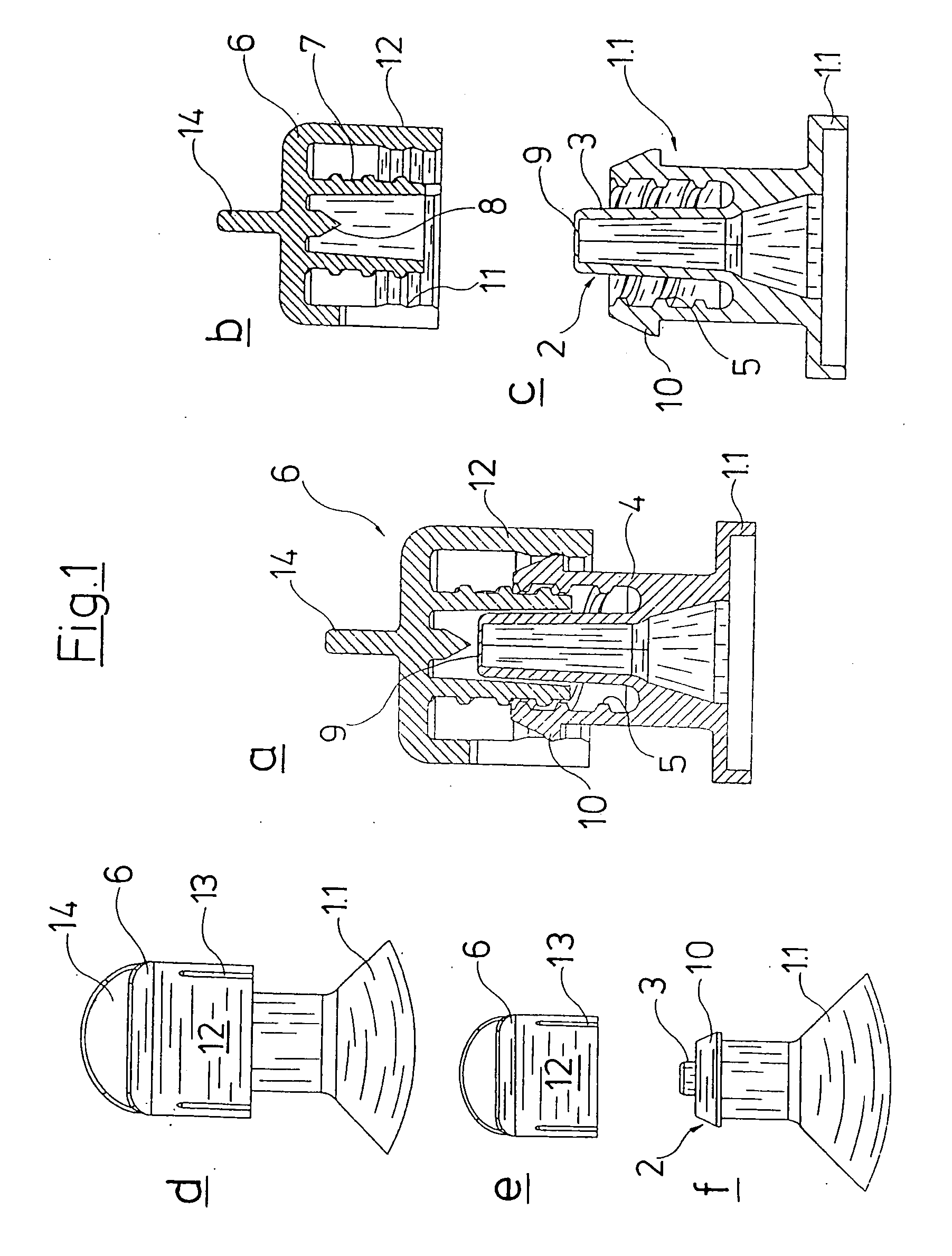
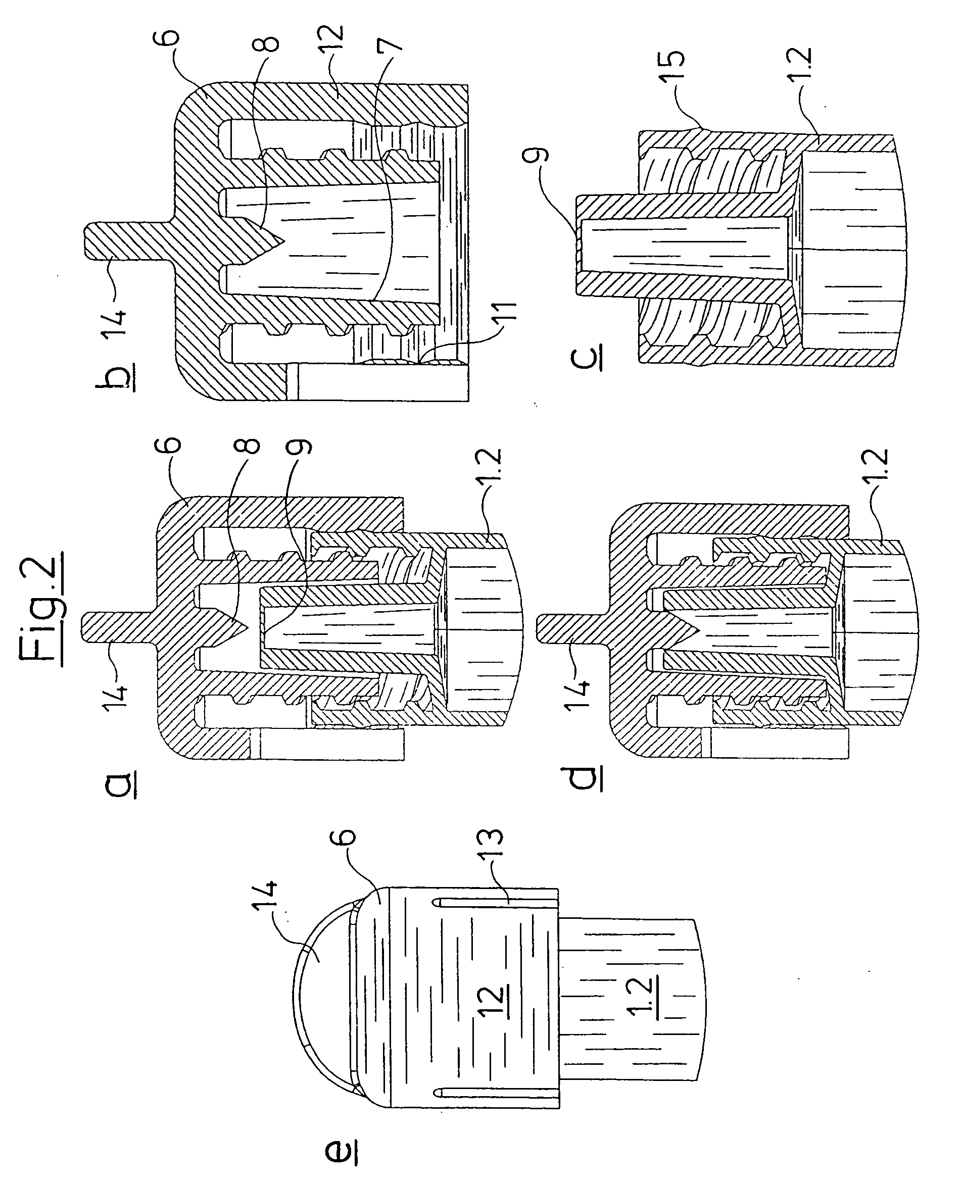
[0044] With the embodiment form according to FIG. 1 a Luer lock connection 2 is integrally formed onto the cannula-side end of the syringe cylinder which is not shown in detail. The Luer lock connection 2 in the known manner consists of a Luer connection 3 which at a distance is surrounded by a cylindrical wall section 4 on whose inner side there is provided a thread 5.

[0045] For protecting the syringe connection formed by the Luer lock connection 2 there is provided a cap 6 which is formed essentially cup-shaped and comprises an inner cylinder 7 which carries an outer thread which may be brought to engage with the thread 5 of the Luer lock connection 2. Within the inner cylinder 7 there is provided a spike 8 which in a first position according to FIG. 1a is arranged at a small distance to a membrane 9 which closes the Luer connection 3 and seals it to the top. As is clearly evident from FIGS. 1a and c the syringe cylinder, Luer lock connection 2 as well as the membrane 9 are formed...


PUM


Abstract

The syringe is a prefillable or prefilled syringe having a syringe cylinder which is delimited to one side by a plunger and which to the other side opens into a syringe connection having a free end closed by a membrane. The syringe cylinder, the syringe connection and the closing membrane are formed as one piece as a plastic injection molded part.

Description

[0001] 1. Field of the Invention[0002] The injection relates to a syringe, in particular to a prefillable or prefilled syringe, having a syringe cylinder with an end provided with a syringe connection having a free end.[0003] 2. Description of the Related Art[0004] Prefilled syringes of this type are known; they are usually manufactured with a syringe cylinder of glass, wherein on that side of the syringe cylinder distant to the syringe plunger there is provided a syringe connection which is sealingly closed by way of a further component.[0005] With the state of the art known from U.S. Pat. No. 5,989,227, this further component is a sealing element which is rigidly connected to and is to remain on the syringe connection. For removing the fluid located in the syringe cylinder this closure must be pierced by way of a cannula. The solution known from U.S. Pat. No. 5,135,496 is more favorable inasmuch as this further component already has a through-bore which at the end is sealed by way...

Claims


Application Information

Patent Timeline
Patent Type & Authority Applications(United States)
IPC IPC(8): A61M5/00A61M5/315B65D51/00
CPCA61M5/347A61M2005/3104A61M5/345A61M5/288A61M2005/3106
Inventor HEINZ, JOCHENSCHILLING, DIETER
Owner TRANSCOJECT
Why Eureka
Try Eureka