Method for identifying obstacles for a motor vehicle, using at least three distance sensors for identifying the laterla extension of an object

a technology of distance sensors and objects, applied in the field of methods for identifying obstacles, can solve problems such as the inability to ensure that each sensor detects the same center of reflection

Inactive Publication Date: 2004-06-17
ROBERT BOSCH GMBH
View PDF7 Cites 4 Cited by
  • Summary
  • Abstract
  • Description
  • Claims
  • Application Information

AI Technical Summary

Benefits of technology

0012] According to the teaching of the present invention, the effect that, in the case of real test objects, multiple centers of reflection are detectable, and that it is therefore not assured that each sensor detects the same center of reflection, is utilized in the sense that in sensor systems having at least three distance sensors, the objects are classified with regard to their spatial dimensioning, in particular with regard to their lateral extension. In a three-sensor system, measurement dropouts of short duration are preferentially backed up by a tracking algorithm, so that each sensor unit does not necessarily have to supply a distance value. In a three + n-sensor system, however, three supporting interpolation nodes are sufficient, but here, too, measurement dropouts of short duration are preferentially backed up by a tracking algorithm.
0013] The concept of the present invention is also based on the assumption and experience that radar beams are reflected predominantly in the direction of the surface normal, which makes it possible to use existing 24-Gigahertz sensors in an advantageous manner according to the present invention.

Problems solved by technology

In measurements using the above-mentioned conventional systems, in particular those based on 24-Gigahertz radar sensors, it was noted that in the case of real test objects, multiple centers of reflection are detectable, and it is therefore not assured that each sensor detects the same center of reflection.

Method used


Image

  • Method for identifying obstacles for a motor vehicle, using at least three distance sensors for identifying the laterla extension of an object
  • Method for identifying obstacles for a motor vehicle, using at least three distance sensors for identifying the laterla extension of an object
  • Method for identifying obstacles for a motor vehicle, using at least three distance sensors for identifying the laterla extension of an object

Examples


first embodiment

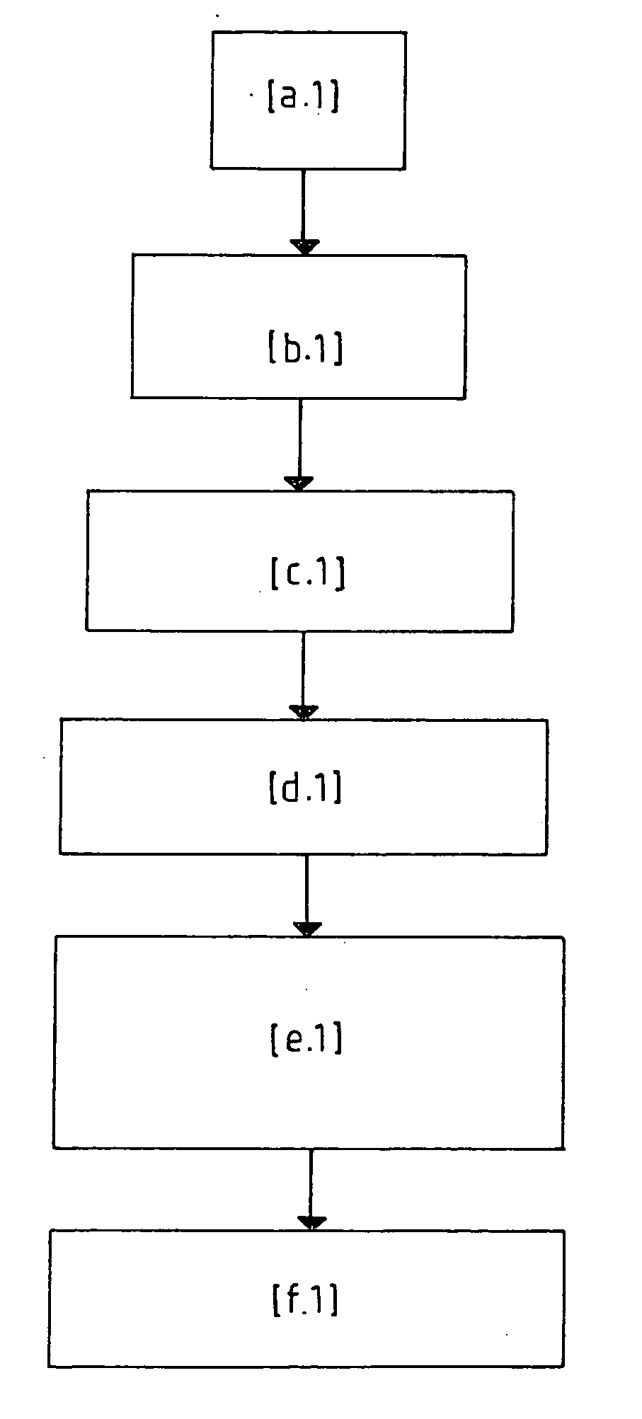
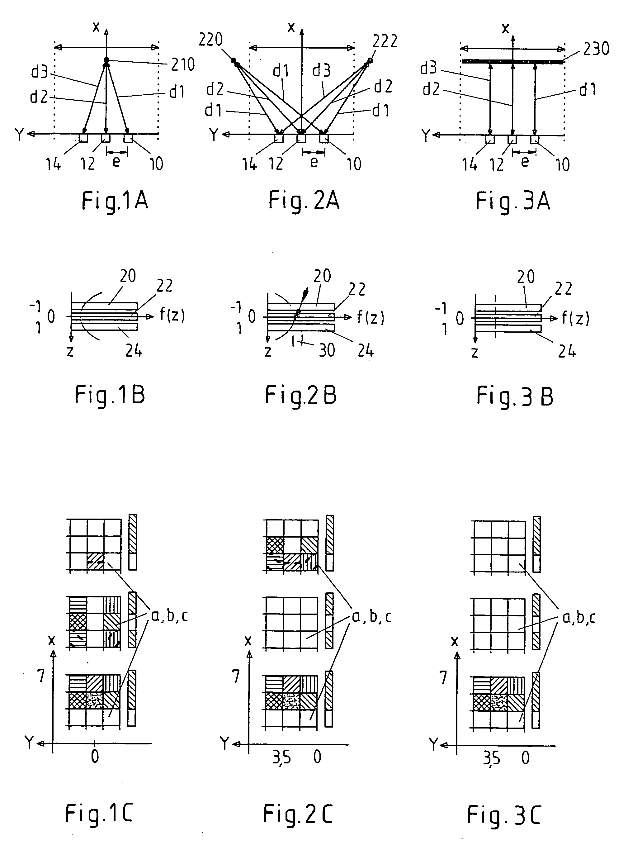
[0053] To accomplish this, according to FIG. 4, distance lists 20 or 22 or 24 of the three sensor units 10 or 12 or 14 are read in in a first procedural step [a.1]. Here, first distance list 20 relates to first distance value d1, second distance list 22 relates to second distance value d2, and third distance list 24 relates to third distance value d3 (see FIGS. 1B, 2B and 3B).

[0054] After reflex clusters 30 are subsequently detected in distance lists 20, 22, 24 in a second procedural step [b.1], coefficients a, b, c are calculated (=third procedural step [c.1]) from the particular smallest distance values d1min, d2min, d3min in clusters 30.

[0055] The next and fourth procedural step [d.1] involves tracking coefficients a, b, c, where the values of the coefficients and their functional derivations based on time t must remain within physically meaningful limits; this means, in other words, that coefficients a, b, c assigned to measured distance values d1, d2, d3, as well as the coeffic...

second embodiment

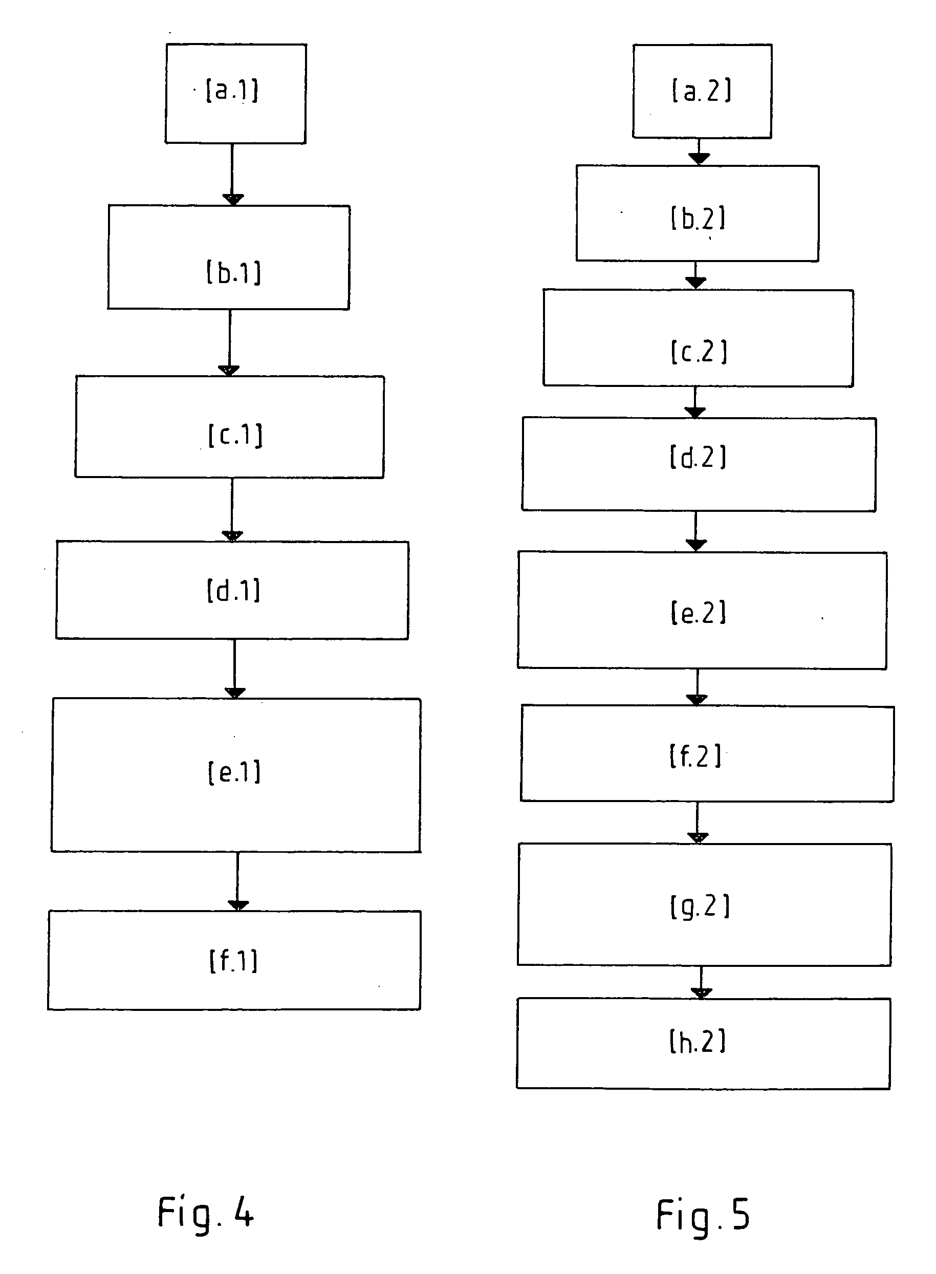
[0062] In contrast to FIG. 4, a subsequent additional seventh procedural step [g.2] then performs a back calculation of the model parabolic coefficients for ideal point-shaped objects at these positions. Based on the deviations of tracked parabolic coefficients a, b, c relative to the back-calculated model parabolic coefficients, the present invention according to FIG. 5 uses a final eighth procedural step [h.2] to generate a measure which describes the general deviation from a point-shaped object, thereby enabling conclusions to be drawn about the extent of the object.

[0063] Regarding the flow chart in the case of the second exemplary embodiment of the present method according to FIG. 5, it should be noted that first six procedural steps [a.2], [b.2], [c.2], [d.2], [e.2], [f.2] correspond to first six procedural steps [a.1], [b.1], [c.1], [d.1], [e.1], [f.1] in the flow chart of the first exemplary embodiment according to FIG. 4, where fifth procedural step [e.2] according to FIG. ...


PUM


Abstract

In order to refine a method, as well as a system (100) for detecting at least one object (210; 220, 222; 230), in particular for detecting its specific parameters such as the relative position of the object (210; 220, 222; 230) or the relative speed of the object (210; 220, 222; 230), such that the objects (210; 220, 222; 230) to be detected may be classified with respect to their spatial dimensioning, in particular with respect to their lateral extension, the spatial, in particular the lateral, extension of the object (210; 220, 222; 230) is detected using at least three distance-resolving units (10; 12; 14), mounted in particular on a means of transportation.

Description

[0001] The present invention relates to a method, as well as a system, for detecting at least one object, in particular for detecting its specific parameters such as the relative position of the object or the relative speed of the object.BACKGROUND INFORMATION[0002] Conventional methods and systems for determining the position of objects using distance sensors such as 24-Gigahertz radar sensors are essentially based on the model of point target objects, where the distance lists of two or more individual 24 Gigahertz distance sensors are used as input variables.[0003] From German Patent Application 42 42 700 A1, an object detection system having a microwave radar sensor is known, which makes possible the detection of objects traveling ahead of a vehicle even at a greater distance. This radar sensor contributes to a vehicle safety system, which continuously processes information regarding the distance and the speed of the vehicle relative to the vehicles traveling ahead of it in a pre...

Claims


Application Information

Patent Timeline
Patent Type & Authority Applications(United States)
IPC IPC(8): B60R21/00G01S13/931G01S7/02G01S13/87
CPCG01S13/878G01S13/931G01S2013/9314G01S2013/9357G01S2013/9332G01S2013/9325G01S2013/9321G01S2013/9315G01S2013/9322
Inventor ZIMMERMANN, UWEPRUKSCH, ACHIM
Owner ROBERT BOSCH GMBH
Why Eureka
Try Eureka