Projector

a projector and projector body technology, applied in the field of projectors, can solve the problems of low light utilization efficiency of projectors, inability to adequately cover human-visible color gamuts, and inability to reduce size and cos

Inactive Publication Date: 2004-06-24
SEIKO EPSON CORP
View PDF6 Cites 17 Cited by
  • Summary
  • Abstract
  • Description
  • Claims
  • Application Information

AI Technical Summary

Problems solved by technology

Although color images of a projector are generally produced by using three kinds of primary color light; i.e., red light (R), green light (G), and blue light (B), unfortunately, as shown in the "RELATED ART" in FIG. 7, the above method cannot sufficiently cover a human-visible color gamut.
Since the projector has a very simple structure and can produce a color projection image with a single electro-optical device, the size and the cost thereof can be easily reduced; however, since four kinds of color light are produced by the color filters, a light utilization efficiency of the projector is very low, whereby it is very difficult to achieve a high luminance of the projection image.
Also, since the pixels are juxtaposed so as to correspond to respective spots of color light, high definition of the projection image is unlikely achieved.
However, since a display time for each kind of color light is short, a light utilization efficiency of the projector is very low, whereby it is very difficult to achieve a high luminance of the projection image.
Also, since the electro-optical device to form an image is required to respond quick

Method used


Image

  • Projector
  • Projector
  • Projector

Examples


first exemplary embodiment

[0036] 1. First Exemplary Embodiment

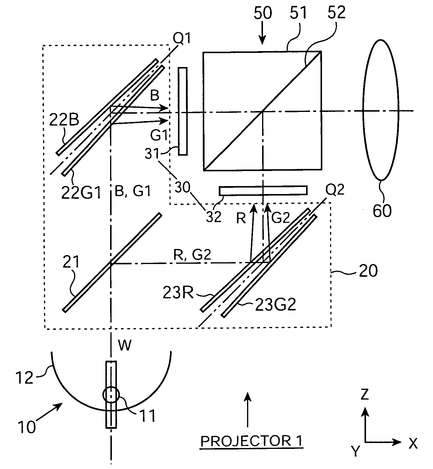
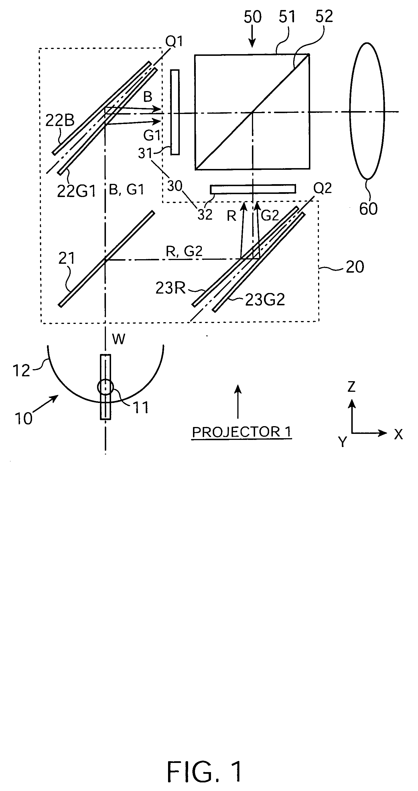
[0037] FIG. 1 shows a schematic structure of a projector 1 according to a first exemplary embodiment of the present invention. The projector 1 is generally formed by a light source 10 to emit light including visible light; a color-separation optical system 20 to separate the light emitted from the light source into four kinds of color light, each having a different wavelength band from the others; a light-modulation optical system 30 to form an optical image of each kind of color light by optically modulating the color light on the basis of external image information; a color-synthesis optical system 50 to form one color image by synthesizing the formed optical images; and a projection optical system 60 to project the formed color image onto a projection surface (not shown).

[0038] Although not shown in FIG. 1, a uniform illumination optical system to make uniform an intensity distribution of an illumination flux incident on the light-modulation op...

second exemplary embodiment

[0059] 2. Second Exemplary Embodiment

[0060] FIG. 8 illustrates the schematic structure of a projector 2 according to a second exemplary embodiment of the present invention. While the projector 2 has substantially the same structure as that of the projector 1 according to the first exemplary embodiment, it has two major differences from the projector 1 in which a polarization-converting optical system to convert light emitted from the light source 10 into a specific polarized flux, and a polarization rotating element to change the polarized state of a polarized flux emitted from the light-modulation optical system 30 are provided. Thus, in the following descriptions including the present exemplary embodiment, the same parts already mentioned are denoted by the same reference numerals and the descriptions thereof will be omitted or simplified.

[0061] The light source 10 and the dichroic mirror 21 serving as the first color-separation optical element have a polarization-converting optic...

modification 1

[0067] Modification 1

[0068] In place of the dichroic mirrors (plate-shaped) 21, 22G1, and 23R and the reflecting mirrors (plate-shaped) 22B and 23G2 in the first and second exemplary embodiments, the color-separation optical system 20 may be formed by a block-shaped dichroic prism. In this case, as described above, an incident angle of light incident on the dichroic surface can be made relatively small, thereby effectively performing color separation of the color light and suppressing occurrence of color unevenness when performing the color separation. Also, since the dichroic surface is unlikely to be warped, the directional separation of the four kinds of color light is accurately performed, thereby enhancing incident efficiency of color light incident on the corresponding sub-pixel, and also reducing or preventing unnecessary color light from being incident on the neighboring sub-pixels of the foregoing sub-pixels so as not to cause color mixture; as a result, a color image havin...


PUM


Abstract

To provide a compact projector in which a projection image is formed by using four kinds of color light so as to expandmagnify an expressible color gamut of the projection image and to achieve an excellent light utilization efficiency, a projector includes a light source, a color-separation optical system, a light-modulation optical system, and a color-synthesis optical system. The color-separation optical system produces four kinds of color light whose output directions are different from each other. The light-modulation optical system includes a first two-color-modulation electro-optical device to modulate any two of the four kinds of color light separated by the color-separation optical system and a second two-color-modulation electro-optical device to modulate the remaining two kinds of color light. Each two two-color-modulation electro-optical device includes a microlens array on a substrate close to the color-separation optical system and a plurality of sub-pixels corresponding to respective microlenses.

Description

[0001] 1. Field of Invention[0002] The present invention relates to projectors having a display feature in a wide color gamut, and more specifically, it relates to a projector which produces four kinds of color light from source light and forms a projection image by using the four kinds of color light.[0003] 2. Description of Related Art[0004] Although color images of a projector are generally produced by using three kinds of primary color light; i.e., red light (R), green light (G), and blue light (B), unfortunately, as shown in the "RELATED ART" in FIG. 7, the above method cannot sufficiently cover a human-visible color gamut. Expansion of a color gamut of the projector is essential in order to faithfully reproduce real and natural colors, and if the projector can independently modulate color light having a wavelength of about 510 nm in addition to the related art red light (R), green light (G), and blue light (B), the expressible color gamut of the projector can be drastically ex...

Claims


Application Information

Patent Timeline
IPC IPC(8): G02F1/13G02B27/18G02B27/28G02F1/1335G03B21/00H04N9/31
CPCH04N9/3197H04N9/3105G02B27/28
Inventor ITO, YOSHITAKA
Owner SEIKO EPSON CORP
Why Eureka
Try Eureka