Substrate processing method and substrate processing apparatus

Inactive Publication Date: 2004-07-01
TOKYO ELECTRON LTD
View PDF6 Cites 24 Cited by
  • Summary
  • Abstract
  • Description
  • Claims
  • Application Information

AI Technical Summary

Benefits of technology

[0010] According to the present invention, the dissolving characteristics of a resist against a developing solution are distributed in the direction of the thickness (depth) of a resist film. As a result, a layer that is easily dissolvable against the developing solution and a layer that is uneasily dissolvable against the developing solution are contrastively formed. In other words, a layer in which the development of the resist is promoted and a layer in which the development of the resist is demoted can be formed. As a result, the reaction speeds of the development can be varied in the direction of the thickness of the film. For example, when a layer that is easily dissolvable against the developing solution is formed on the front surface side of the resist film, only the front side can be developed. Thus, even if the exposure depths and exposure widths vary with half-exposed regions, the uniformity of the residual film of the half-exposed regions can be improved. As a result, the distances of electrodes that will be formed later become uniform.
[0043] According to such structure, the first resist that exposure-reacts with the first exposure energy and the second resist that exposure-reacts with the second exposure energy can be coated in this order on the substrate. Thus, since the first resist and the second resist are half-exposed with a half-tone mask having regions with different transmittances, for example the first resist does not exposure-react and the second resist exposure-reacts. As a result, the exposure reaction of the first resist can be separated from the exposure reaction of the second resist. Thus, after the resists are half-exposed, the uniformity of the residual film of the resists can be improved.

Problems solved by technology

If the resist does not contain sufficient moisture, even if the resist is exposed, it hardly reacts.

Method used


Image

  • Substrate processing method and substrate processing apparatus
  • Substrate processing method and substrate processing apparatus
  • Substrate processing method and substrate processing apparatus

Examples


first embodiment

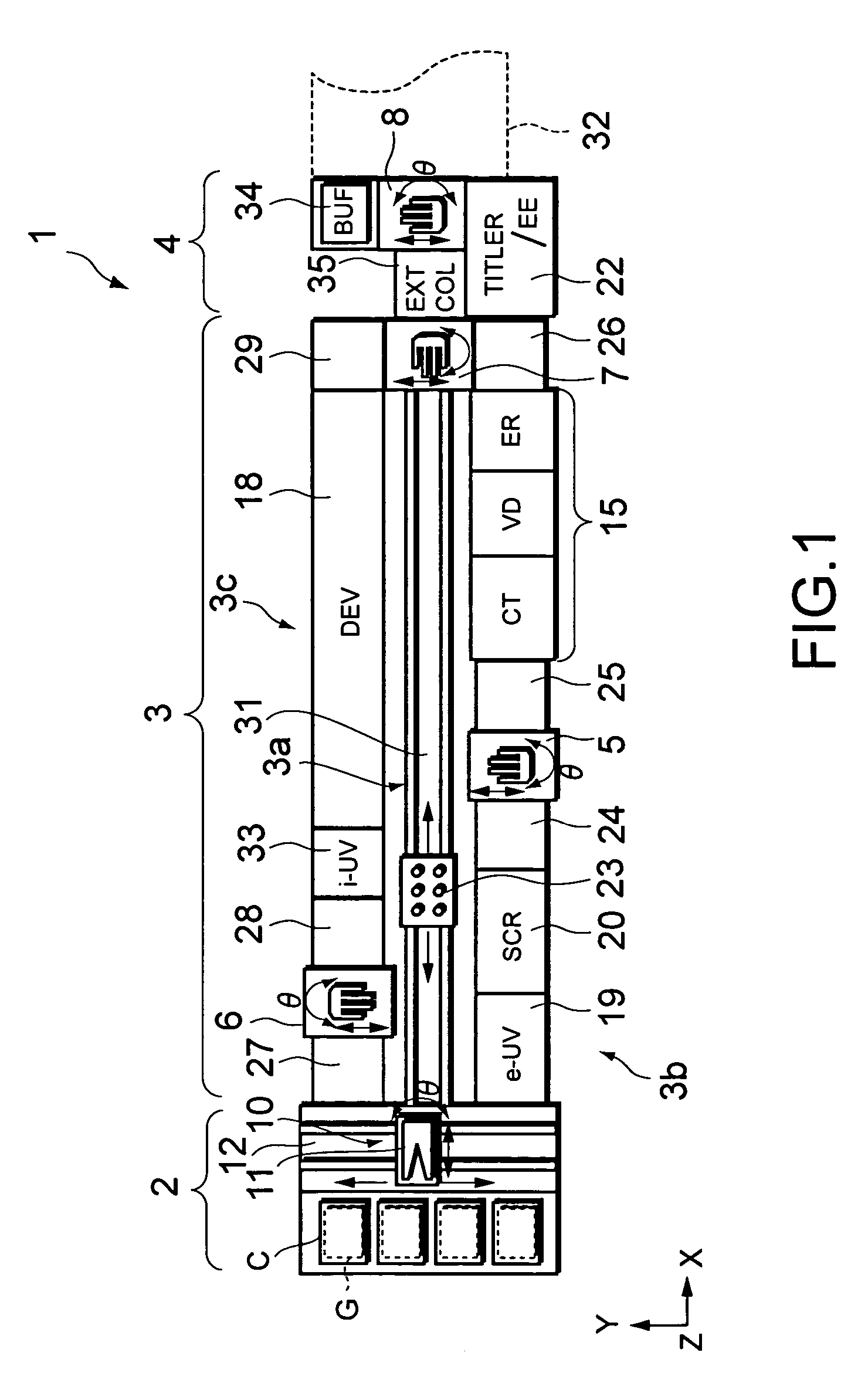
[0087] FIG. 1 is a plan view showing a coating and developing process system for an LCD substrate according to a first embodiment of the present invention. FIG. 2 is a front view showing the system. FIG. 3 is a rear view showing the system.

[0088] The coating and developing process system 1 has a cassette station 2, a process portion 3, and an interface portion 4. On the cassette station 2, cassettes C are placed. Each of the cassettes C accommodates a plurality of glass substrates G. The process portion 3 has a plurality of process units that perform a sequence of processes including a resist coating process and a resist developing process for a substrate G. The interface portion 4 transfers a substrate G with an exposing unit 32. The cassette station 2 and the interface portion 4 are disposed at both ends of the process portion 3.

[0089] The cassette station 2 has a conveying mechanism 10 that conveys an LCD substrate between a cassette C and the process portion 3. The cassette stat...

second embodiment

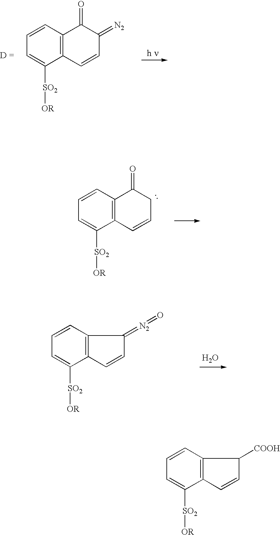
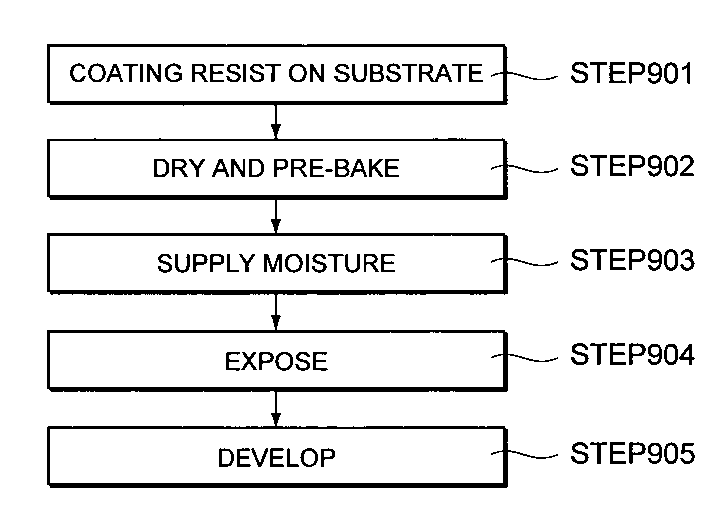
[0123] Next, with reference to FIG. 9, FIG. 10A to FIG. 10F, FIG. 11A to FIG. 11D, and FIG. 12A to FIG. 12C, an embodiment that controls the amount of moisture contained in a resist formed on a substrate so as to control the distribution of a characteristic of the reaction of the resist against exposure light will be described as a second embodiment of the present invention. According to the present embodiment, for example a g-line resist is used.

[0124] FIG. 9 is a flow chart showing steps according to the present invention. FIG. 10A to FIG. 10F and FIG. 11A to FIG. 11D are sectional views showing the steps according to the present invention and the related art. FIG. 10A, FIG. 10B, and FIG. 10C are sectional views showing steps according to the present invention. FIG. 10D, FIG. 10E, and FIG. 10F are sectional views showing steps according to the related art. In the following description, the steps according to the present invention and the steps according to the related art will be ...

third embodiment

[0131] Next, with reference to FIG. 12A to FIG. 12C, FIG. 13A to FIG. 13D, FIG. 14A, FIG. 15A to FIG. 15B, and FIG. 16, an embodiment that forms an uneasily dissolvable layer on the front surface side of a resist will be described as a third embodiment of the present invention.

[0132] FIG. 14 is a flow chart showing steps according to the present embodiment. FIG. 12A to FIG. 12C and FIG. 13A to FIG. 13D are sectional views showing the steps of the present embodiment. FIG. 15A, FIG. 15B, and FIG. 16 are graphs showing the relation of exposure energy and film thickness of a resist that has been developed.

[0133] As shown in FIG. 12A, a resist R is coated on a substrate (at step 1401). The resist R coated on the substrate is dried by the reduced pressure drying process unit (VD) under reduced pressure. A pre-baking unit of the thermal process block 26 performs a heating process for the resist R (at step 1402).

[0134] Thereafter, as shown in FIG. 12B, the developing solution 50 used for a ...


PUM

PropertyMeasurementUnit
temperatureaaaaaaaaaa
atmospheric pressureaaaaaaaaaa

Abstract

A processing chamber actually performs a heating process for a substrate. The processing chamber has an upper plate, a lower plate, and an exhaust opening. The upper plate heats a resist from a front surface of the substrate. The lower plate heats the resist from a rear surface of the substrate. The exhaust opening exhausts gas from the processing chamber. The upper plate is disposed in such a manner that it can be raised and lowered in the processing chamber by an upper air cylinder that composes an upper driving mechanism. The lower plate is disposed on a floor of the processing chamber. The exhaust opening is connected to a pump through a pipe. Heating temperature and heating time of the upper plate and the lower plate are controlled by a heating control portion. A pressure in the processing chamber is controlled by a pump. The pump is controlled by a pressure controlling portion.

Description

[0001] 1. Field of the Invention[0002] The present invention relates to a substrate processing method and a substrate processing apparatus for processing a glass substrate and a semiconductor substrate used for a liquid crystal display device and so forth.[0003] 2. Description of the Related Art[0004] In a producing process for a liquid crystal display (LCD), a photolithography technology for producing a semiconductor device is also used to form an indium tin oxide (ITO) thin film and an electrode pattern on a glass substrate for an LCD. In the photolithography technology, photoresist is coated on a glass substrate. Thereafter, the photoresist on the glass substrate is exposed and developed.[0005] As an example of the exposing method, a so-called half-exposing method is known. In the ordinary exposing method, a portion not to be exposed is covered with a mask so as to insulate it from light. In contrast, in the half-exposing method, a half-tone mask or the like that has regions with...

Claims


Application Information

Patent Timeline
Patent Type & Authority Applications(United States)
IPC IPC(8): H01L21/027G03F7/00G03F7/16G03F7/20H01L21/00
CPCG03F7/168G03F7/2022H01L21/67178H01L21/67173H01L21/6715H01L21/027
Inventor SHIRAISHI, MASATOSHINAKAMA, MASATSUGUTAKAMORI, HIDEYUKI
Owner TOKYO ELECTRON LTD
Why Eureka
Try Eureka