
Smart resolution valve pressure control

a valve pressure and resolution technology, applied in hydrodynamic testing, instruments, braking systems, etc., can solve the problems of 1 or 2 psi, inability to achieve brake cylinder pressure changes, and use of single 20 ms time steps as limitations in certain present applications, so as to improve control accuracy, improve control accuracy, and achieve accurate pressure output.

Inactive Publication Date: 2004-07-08
WESTINGHOUSE AIR BRAKE TECH CORP
View PDF5 Cites 5 Cited by
  • Summary
  • Abstract
  • Description
  • Claims
  • Application Information

AI Technical Summary

Benefits of technology

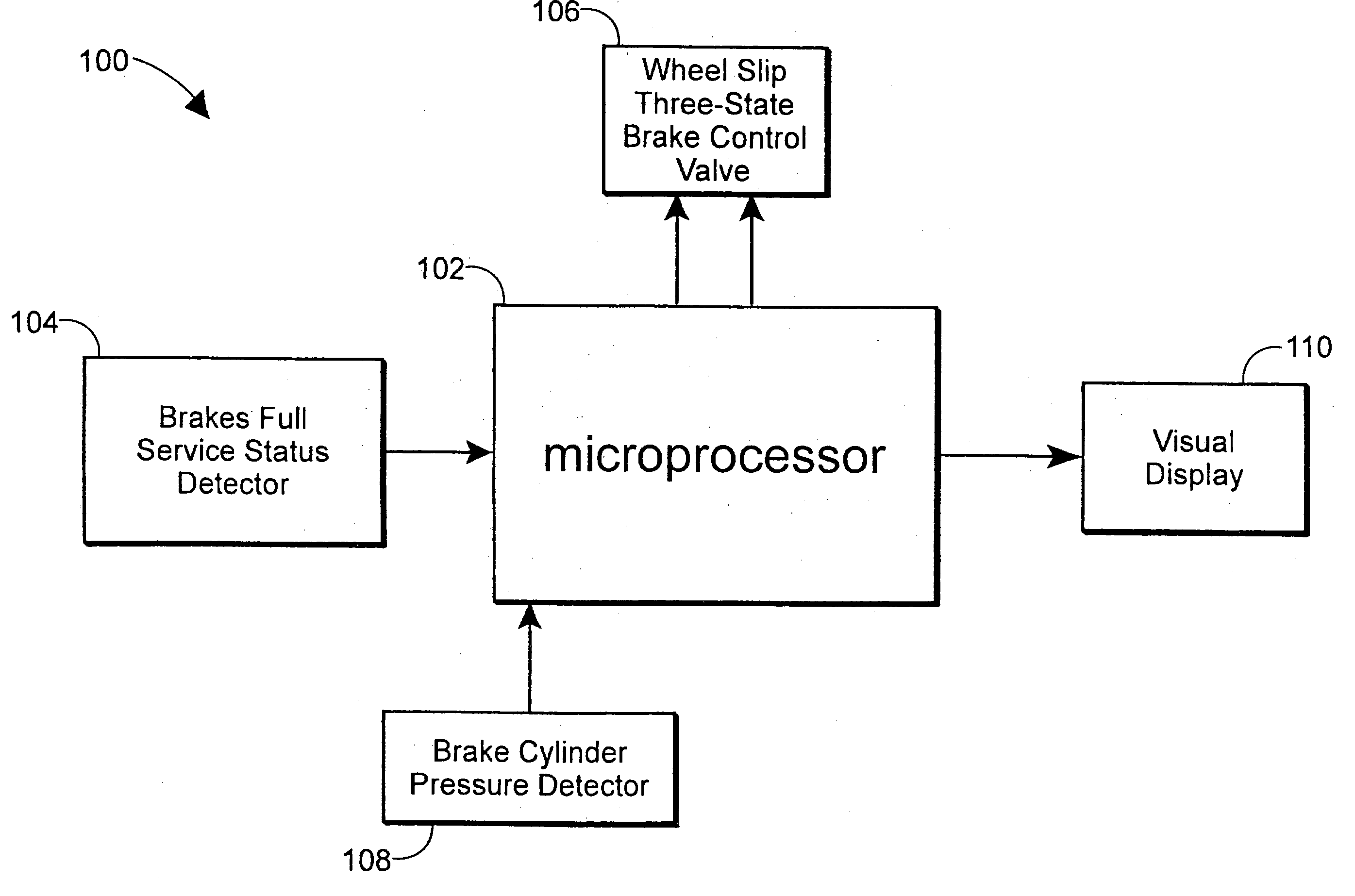
[0010] Another object of the present invention is to provide a smart resolution valve pressure control system to communicate and interface with the valve every millisecond instead of every 20 ms to allow a greater degree of valve control, which improves control accuracy.
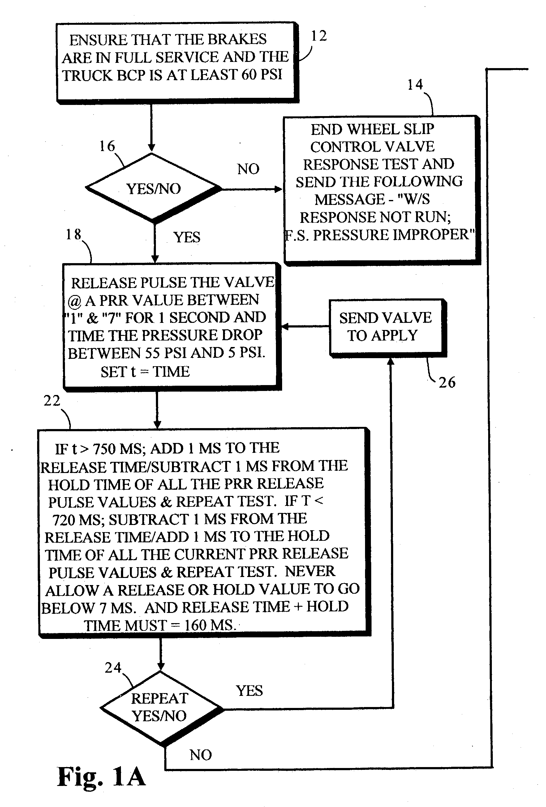
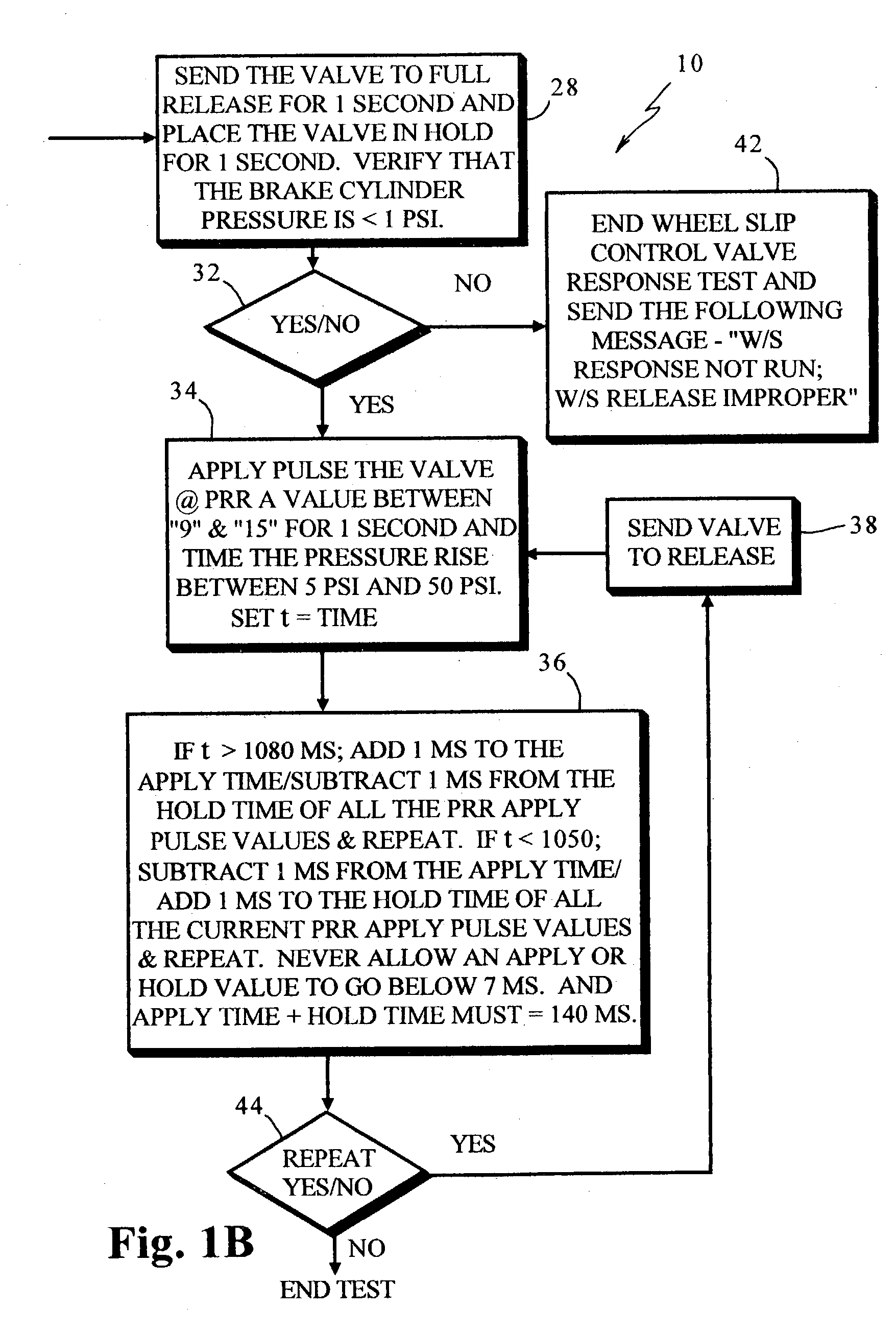
[0011] Yet another object of the present invention is to provide a smart resolution valve pressure control system to provide an accurate pressure output within a desired bandwidth which utilizes a smart algorithm that relies on a self-adjusting calibrated pulse time for a minimum pressure adjustment.
[0012] Yet another object of the present invention is to provide a smart resolution valve pressure control system to reduce the valve cycles significantly and to thereby increase the valve life.
[0013] Still another object of the present invention is to provide a smart resolution valve pressure control system to provide an improved shorter interrupt control time.

Problems solved by technology

The use of the single 20 ms time step has become a limitation in certain present applications.
For example, several three-state valves that were used to control brake cylinder pressure have had problems maintaining stability with tight tolerances, and in some configurations cannot achieve brake cylinder pressure changes as small as 1 or 2 psi.
Even if the system is successfully calibrated to achieve these tight tolerances initially, they cannot be maintained for long time periods as the magnet valve components wear.

Method used


Image

  • Smart resolution valve pressure control
  • Smart resolution valve pressure control
  • Smart resolution valve pressure control

Examples


Embodiment Construction

[0021] Prior to proceeding with the more detailed description of the invention, it should be noted that for the sake of clarity, identical components of the smart resolution valve pressure control, which have identical functions, have been identified with identical reference letters throughout the views illustrated in the drawings.

[0022] In the presently preferred embodiment, this invention provides a method and apparatus to allow any pressure control system using valve state pulsing to modify airflow at an optimum and consistent range of operation. The presently preferred embodiment of this invention also provides a plurality of valve-control pressure interrupt commands between the primary control interrupts of a microprocessor. The presently preferred embodiment of this invention also provides communication and interface with the valve every millisecond instead of every 20 ms to allow a greater degree of valve control, which improves control accuracy.

[0023] Reference is now made t...


PUM


Abstract

The Smart Resolution Valve Pressure Control System allows any pressure control system using valve state pulsing to modify airflow at an optimum and consistent range of operation thereby enhancing control accuracy and increasing the useable cycle life of any valve combination used.

Description

[0001] The present invention generally relates to valve pressure control and, more particularly, relates to the valve pressure control as it relates to brake and wheel slip control on a transit railway vehicle and, still more particularly, to a microprocessor for controlling the control logic of a passenger transit vehicle and, even more particularly, to a microprocessor system designed to control the magnet valves, apply and release the magnet valves for proper fixed pulse timing to improve the lifecycle of these valves.[0002] There are known, in the prior art, many transit systems that require brake and / or wheel slip control and use microprocessors that run wheel slip calculations and control logic at 20 milliseconds (ms) intervals, and which generally use single 20 ms interrupts. The 20 ms interrupt control has proven sufficient for most applications in the past with simpler system interfaces and larger brake cylinder pressure tolerances. However, since current and future systems...

Claims


Application Information

Patent Timeline
IPC IPC(8): B60T8/94B60T8/1761B60T8/36B60T13/66B60T13/68B60T15/36B60T17/22B61H11/04
CPCB60T13/665Y10T74/19251B60T17/221B60T13/686
Inventor SCHWEIKERT, DAVID E.WOOD, JAMES A.
Owner WESTINGHOUSE AIR BRAKE TECH CORP
Learn More