Method and apparatus for measuring Raman gain, method and apparatus for controlling Raman gain, and Raman amplifier

a technology of raman gain and amplifier, which is applied in the direction of instruments, optical apparatus testing, structural/machine measurement, etc., can solve the problems of inability to flexiblely set a measurement interval, inability to measure, and inability to measure,

Inactive Publication Date: 2004-08-19
NEC CORP
View PDF6 Cites 17 Cited by
  • Summary
  • Abstract
  • Description
  • Claims
  • Application Information

AI Technical Summary

Problems solved by technology

As described above, because of difficulties in workability, there was a demand for means of measuring the gain efficiency only by an operation at one end of the transmission line.
Moreover, when, with respect to excitation wavelengths of plural types, Raman gain efficiencies of desired wavelengths are required to be obtained, respectively, different test lights having wavelengths of the same numbe

Method used


Image

  • Method and apparatus for measuring Raman gain, method and apparatus for controlling Raman gain, and Raman amplifier
  • Method and apparatus for measuring Raman gain, method and apparatus for controlling Raman gain, and Raman amplifier
  • Method and apparatus for measuring Raman gain, method and apparatus for controlling Raman gain, and Raman amplifier

Examples


first embodiment

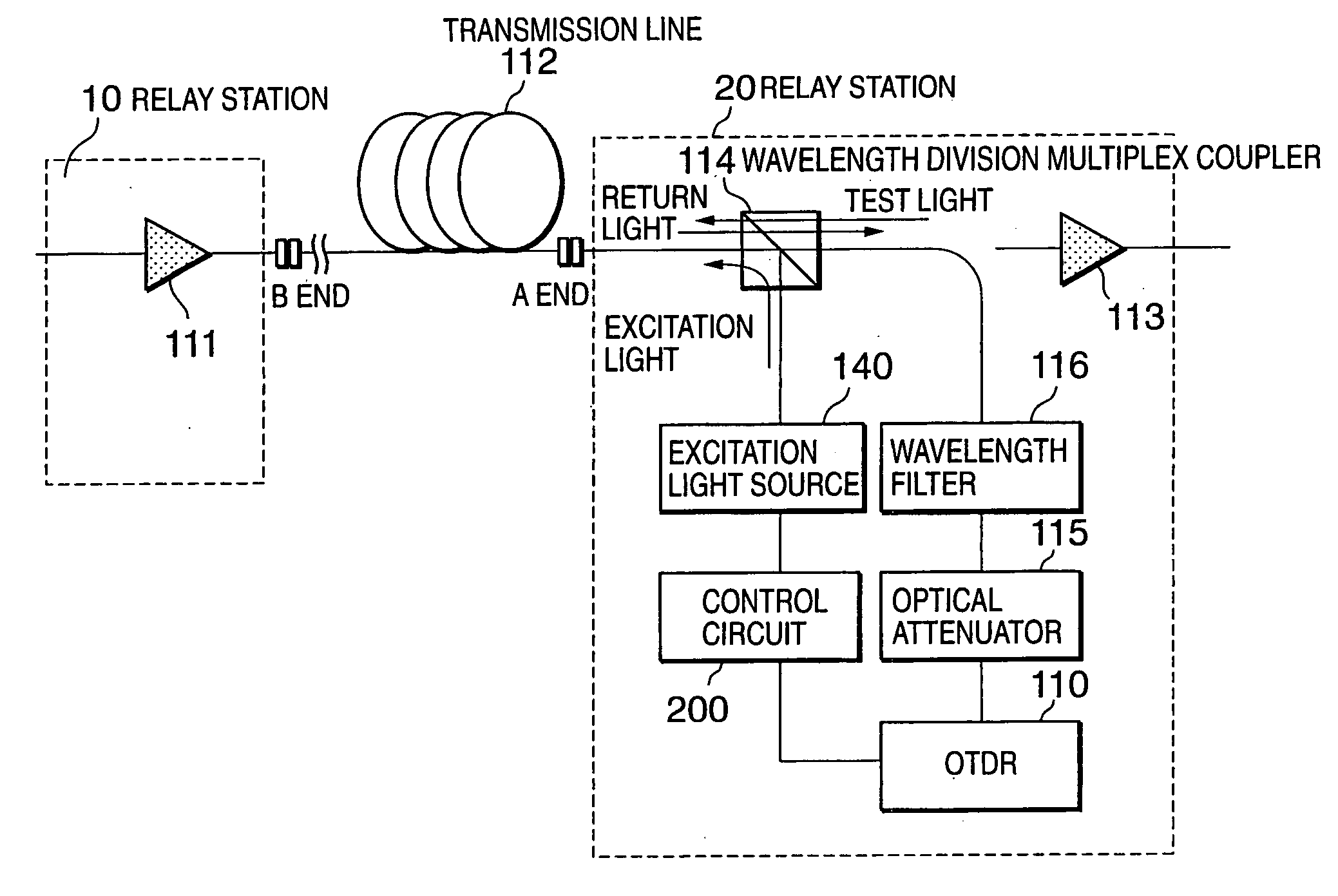
[0038] FIG. 3 is a constitutional view showing a constitution of the present invention. In the constitution of FIG. 3, a WDM coupler 114 for multiplexing / demultiplexing an excitation light wavelength and a test light wavelength is connected to one end of a transmission line. An excitation light source 140 is provided in an excitation light wavelength port of the WDM coupler 114; and a wavelength filter 116, an optical attenuator 115 and an OTDR device 110 are serially connected in this order to a test light wavelength port thereof. In FIG. 3, a Raman gain is measured by use of the wavelength filter 116, the optical attenuator 115, the OTDR device 110 and the WDM coupler 114.

[0039] In the embodiment, measurement of a Raman gain efficiency is conducted by use of the optical time-domain reflectometry (OTDR) device 110.

[0040] OTDR is a technique for measuring distributed losses in an optical fiber transmission line by making pulsed light incident from one end of the optical fiber transm...

second embodiment

[0052] Next, description will be made for a second embodiment of the present invention. In the foregoing first embodiment, the Raman gain efficiency is obtained by use of the propagation loss detected from the return light generated in short of the vicinity of B end of the transmission line. However, there is a case, as shown in FIG. 7, where B end cannot be detected due to noise in a transmission line having a large loss in a test light wavelength. In such a case, a gain efficiency can be obtained based on return light generated at a point (B' point of FIG. 7) which is not buried in the noise. However, a significant attenuation of an excitation light power at B' point leads to generation of no Raman gain. In other words, OTDR graphs in a state of stopping an excitation light output and in a state of outputting the excitation light are required to be parallel to each other. When the OTDR graphs in the state of stopping the excitation light output and in the state of outputting the e...

third embodiment

[0054] Description will be made for a third embodiment of the present invention. The first embodiment showed the Raman gain efficiency in the case where the test light is lower in frequency than the excitation light by 13 THz. However, not being limited to the above, a Raman gain efficiency can be measured regarding other wavelength intervals. For example, in the same SMF as that of the first embodiment, when a test light wavelength of 1550.0 nm and an excitation light wavelength of 1463.8 nm are used and an excitation light output power is set to 166 mW, a Raman gain of 4.6 dB and a Raman gain efficiency of 27.7 dB / W are obtained. FIG. 8 shows a relation among the excitation light wavelength, the test light wavelength and a Raman gain profile in the embodiment.


PUM


Abstract

A Raman amplifier of the present invention includes a loss measuring unit (110) for measuring loss distribution of an object of measurement by OTDR based on reflected light with respect to outputted test light; an optical coupler (114) in which the test light is supplied to a first input terminal thereof and one of output terminals thereof is connected to an optical fiber transmission line; a wavelength filter (116) inserted between the loss measuring unit (110) and the optical coupler (114); a control circuit (200) for generating a control signal for reducing an error signal obtained by comparing a Raman gain obtained with a reference value; and an excitation light source (140) for changing an excitation light power based on the control signal.

Description

[0001] This application is a division of co-pending application Ser. No. 10 / 107,392, filed on Mar. 28, 2002, the entire contents of which are hereby incorporated by reference.[0002] 1. Field of the Invention[0003] The present invention relates to a method and apparatus for measuring a Raman gain, a method and apparatus for controlling a Raman gain and a Raman amplifier, which are used in optical communications and the like. Particularly, the present invention relates to a method for measuring a Raman gain, which is capable of measuring a Raman gain at one end of an optical fiber transmission line, and an apparatus thereof, to a method and apparatus for controlling a Raman gain and to a Raman amplifier.[0004] 2. Description of Related Art[0005] Along with exploitation of wavelength bands utilizing low-loss optical fibers and low-loss wavelength bands and with development of amplification technologies, prolongation of optical fiber transmissions has been advancing these days. To perfo...

Claims


Application Information

Patent Timeline
IPC IPC(8): G01M11/00G01M11/02G02F1/35H01S3/06H01S3/067H01S3/10H01S3/131H01S3/30
CPCG01M11/3145G01M11/3154H01S3/06754H01S3/302H01S3/1301H04B10/0731H04B10/2916H01S3/0014H04B10/071H01S3/13013H01S3/1001
Inventor SOBE, MASAAKIYANO, YUTAKA
Owner NEC CORP
Why Eureka
Try Eureka