High sensitivity radio receiver

a radio receiver and high-sensitivity technology, applied in the field of high-sensitivity radio receivers, can solve the problems of difficult to stabilize the temperature of ld5 and extremely difficult to secure the dynamic range dr

Inactive Publication Date: 2004-08-19
NTT DOCOMO INC
View PDF3 Cites 52 Cited by
  • Summary
  • Abstract
  • Description
  • Claims
  • Application Information

AI Technical Summary

Benefits of technology

[0019] As a result of the described arrangement, since the LD is maintained below a normal temperature, it affords a greater dynamic range than in the prior art, allowing an increase in the number of multiplexible channels m. If the receiver is subject to a temperature variation as experienced in the prior art, such allowance makes the receiver less susceptible to the influence of a temperature variation when an equal number of channels is considered. Since the reception bandpass filter means and the low noise reception amplifier are also cooled, the occurrence of thermal noises is minimized, contributing to the low loss / low noise.

Problems solved by technology

However, it is difficult to stabilize the temperature of LD5 by using Peltier elements in an outdoor environment where the environmental temperature varies largely.
For this reason, it has been extremely difficult to secure the dynamic range DR which accomplishes a desired number of multiplexible channels m in a stable manner despite any variation in the environmental temperature when conventional high sensitivity receiver is installed outdoors.

Method used


Image

  • High sensitivity radio receiver
  • High sensitivity radio receiver
  • High sensitivity radio receiver

Examples


embodiment 1

[0054] Embodiment 1

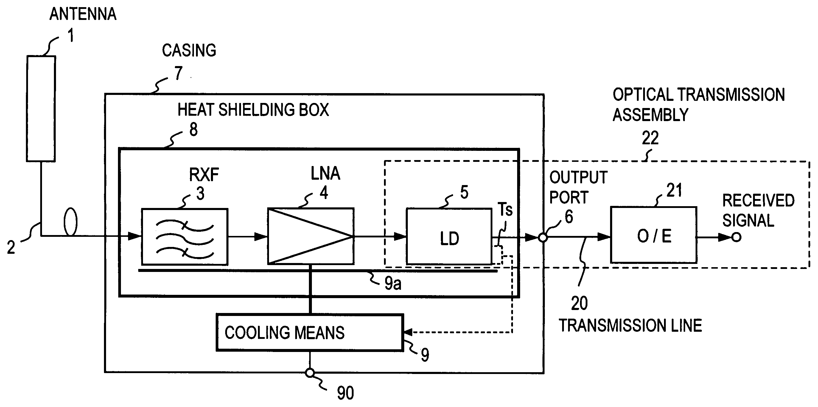
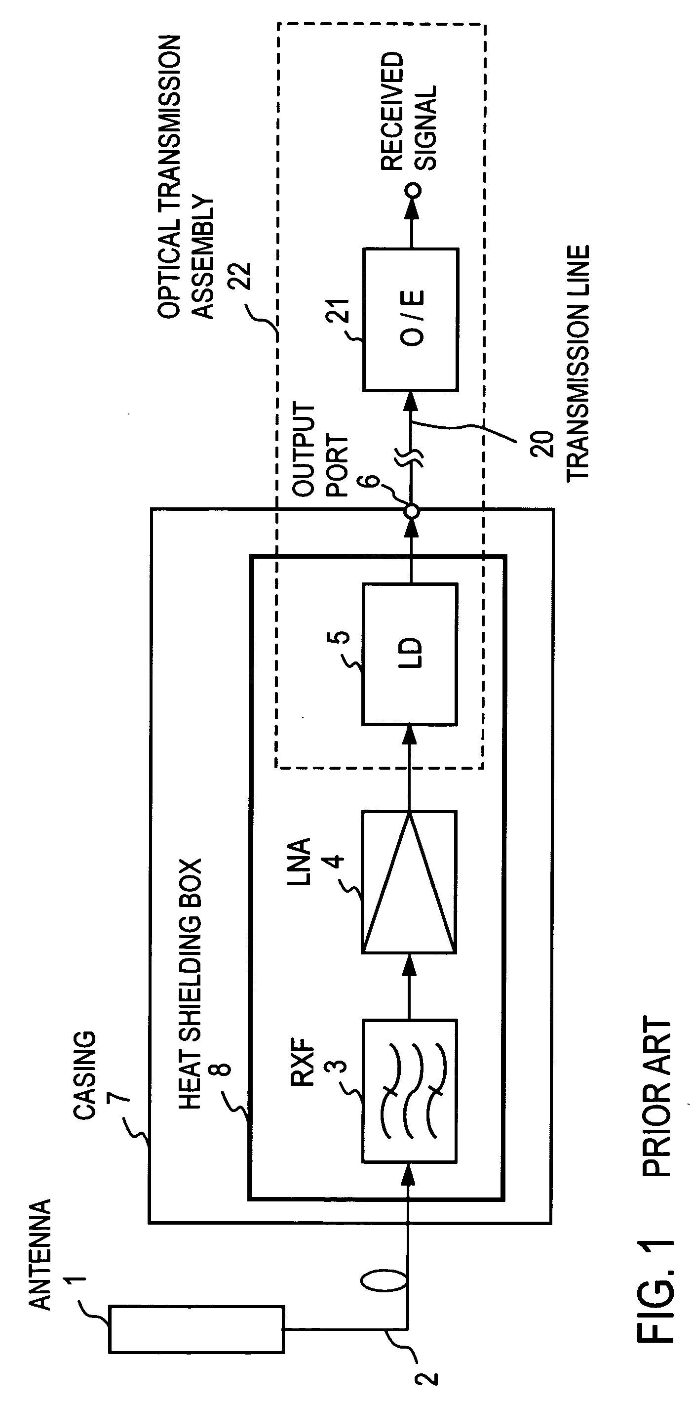
[0055] FIG. 5 shows an embodiment of a high sensitivity radio receiver according to the present invention, and parts corresponding to those shown in FIG. 1 are designated by like reference characters as used before. In the description to follow, parts shown which correspond to those illustrated in the drawings which have been mentioned above are designated by like reference characters, and their duplicate description will be omitted. In comparison to the arrangement shown in FIG. 1, this embodiment is distinct in that RXF3 LNA4 and LD5 are confined in a heat shielding box 8 which may comprise a Dewar flask, for example, and are cooled by cooling means 9 which operate in response to a power supply from the outside through a power terminal 90. In this example, RXF3, LNA4 and LD5 are cooled by a single cooling unit. The cooling means 9 has a cold head on which a cooling member 9a is mounted, and RXF3, LNA4 and LD5 are mounted on the cooling member 9a. These devices a...

embodiment 2

[0063] Embodiment 2

[0064] In the embodiment 2, RXF3, LNA4 and LD5 are divided in two groups, one of which is cooled by a first cooling unit while the other is cooled by a second cooling unit.

[0065] FIG. 7 shows an embodiment where RXF3 and LNA4 on one hand and LD5 on the other hand are cooled to different temperatures.

[0066] What is distinct in this embodiment in comparison to the arrangement shown in FIG. 5 is the fact that RXF3 and LNA4 are directly mounted on the cooling member 9a while LD5 is mounted thereon through a heat resistance member 10-1 interposed therebetween. This means that RXF3 and LNA4 are directly cooled by the cooling member 9a, but LD5 is cooled by the cooling member 9a through the heat resistance member 10-1. The heat resistance member 10-1 has a relatively low thermal conductivity, and an aluminum plate or a ceramic plate having a thermal conductivity which is less than a copper plate is used, for example.

[0067] With this arrangement, RXF3 is maintained at a f...

embodiment 3

[0079] Embodiment 3

[0080] Embodiment 3 use a plurality of cooling means which are provided as a plurality of cooling units of cooling means 9. This embodiment is shown in FIG. 11.

[0081] A distinction of this embodiment over the arrangement shown in FIG. 1 resides in the fact that RXF3 and LNA4 are cooled by first cooling means 9-1 while LD5 is cooled by second cooling means 9-2. Specifically, RXF3 and LNA4 are mounted on the cooling member 9a1 in the first cooling means 9-1 to be cooled and maintained at a first temperature in a stable manner for a prolonged period of time. LD5 is mounted on the cooling member 9a2 of the second cooling means 9-2 to be cooled and is maintained at a second temperature in a stable manner for a prolonged period of time. The purpose of providing the first and the second cooling means 9-1 and 9-2 is to allow the first temperature for RXF3 and the second temperature for LD5 to be independently set up. Cooling means 9-1 and 9-2 form together cooling means 9...


PUM


Abstract

The invention relates to a high sensitivity receiver installed outdoors which may be used in a base station of a mobile communication system, for example. A received radio frequency signal is converted into a signal in a desired frequency band by a reception bandpass filter RXF3, is subject to a low noise amplification to a desired level by a low noise reception amplifier LNA4, and the amplified signal is converted into an optical signal by a laser diode LD5. RXF3, LNA4 and LD5 are confined in a heat shielding box. LD5 is cooled by cooling means to the order of critical temperature where RXF3, for example, assumes a superconducting state, whereby the dynamic range is increased and stabilized.

Description

[0001] The present invention relates to a radio receiver which may be used in a mobile communication base station system, for example, and in particular, to a high sensitivity radio receiver which exhibits an improved reception sensitivity achieved through the cooling of a radio frequency receiver section and which converts a received signal into an optical signal to be delivered as an output.PRIOR ART[0002] FIG. 1 shows a block diagram of a conventional high sensitivity radio receiver.[0003] The conventional high sensitivity receiver comprises an antenna 1, an antenna feeder 2 for transmitting a signal received by the antenna 1, a reception bandpass filter (hereafter referred to as "RXF") 3 for selecting a signal in a desired band, a low noise reception amplifier (hereafter referred to as "LNA") 4 for amplifying an output from RXF3 to a desired level, a laser diode (hereafter referred to as "LD") 5, an output port 6, a transmission line 20 formed by an optical fiber cable, and an o...

Claims


Application Information

Patent Timeline
Patent Type & Authority Applications(United States)
IPC IPC(8): H04B1/036H04B1/18
CPCH04B1/18H04B1/036
Inventor CHEN, NINGTARUSAWA, YOSHIAKISATOH, KEINARAHASHI, SHOICHITERADA, NORIYOSHINOJIMA, TOSHIO
Owner NTT DOCOMO INC
Why Eureka
Try Eureka