Piston pump

a technology of piston pump and piston plate, which is applied in the direction of positive displacement liquid engine, liquid fuel engine, braking system, etc., can solve the problems of large size of known brake system, and increased production cos

Inactive Publication Date: 2004-08-26
ROBERT BOSCH GMBH
View PDF5 Cites 39 Cited by
  • Summary
  • Abstract
  • Description
  • Claims
  • Application Information

AI Technical Summary

Problems solved by technology

Because of the pressure damper, the known vehicle brake system is relatively large as well, and i

Method used


Image

  • Piston pump
  • Piston pump
  • Piston pump

Examples


Embodiment Construction

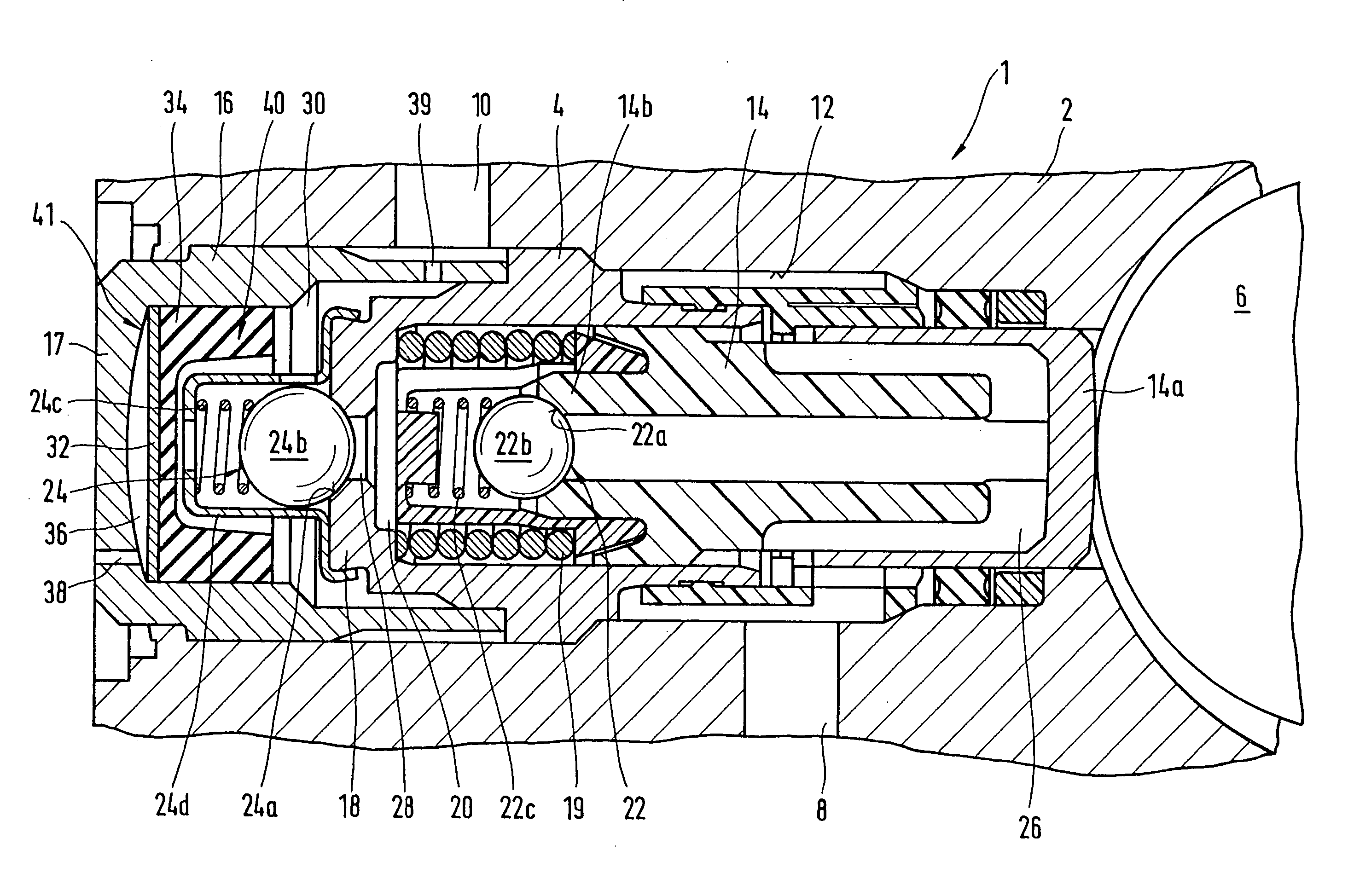
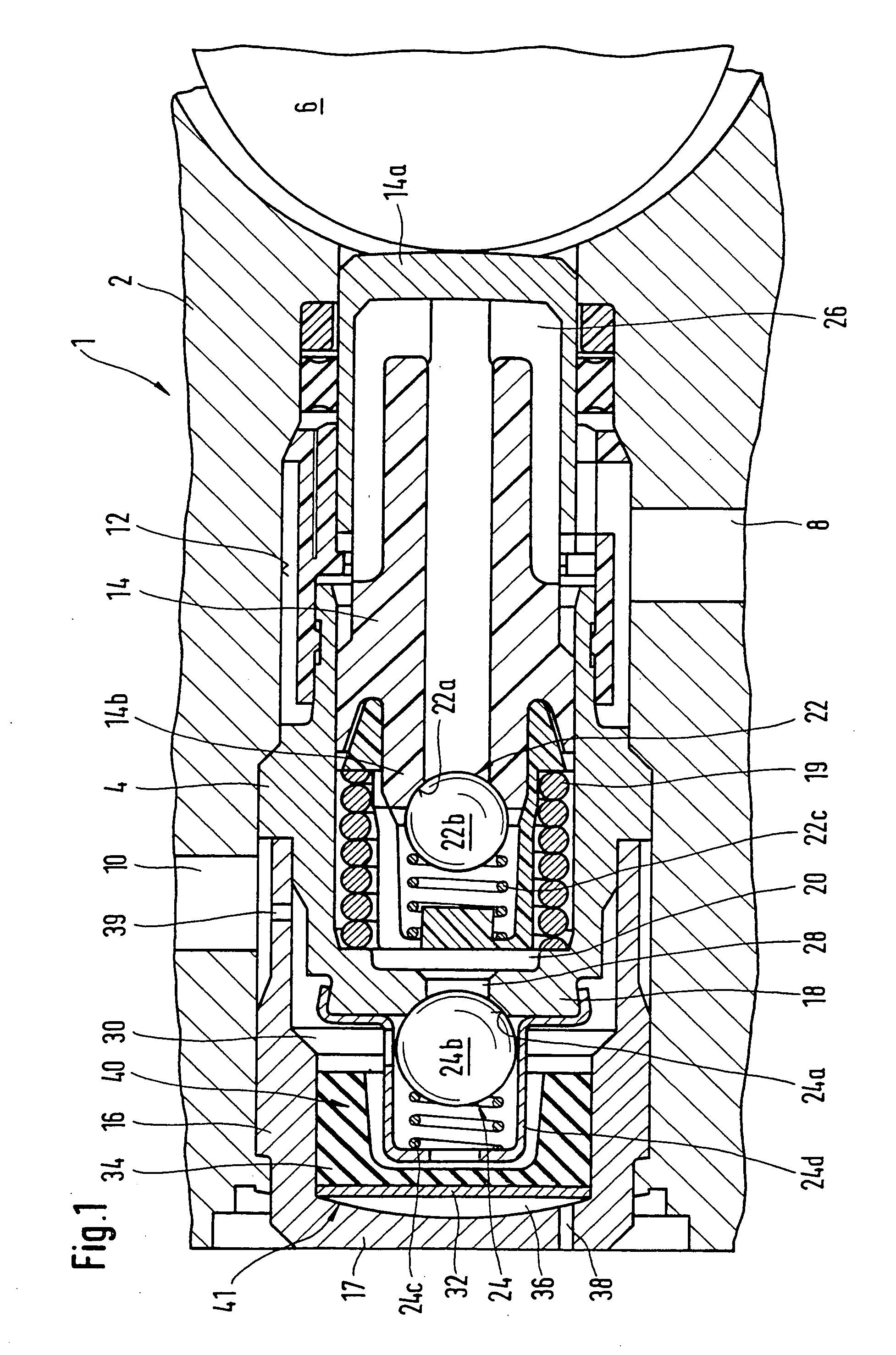
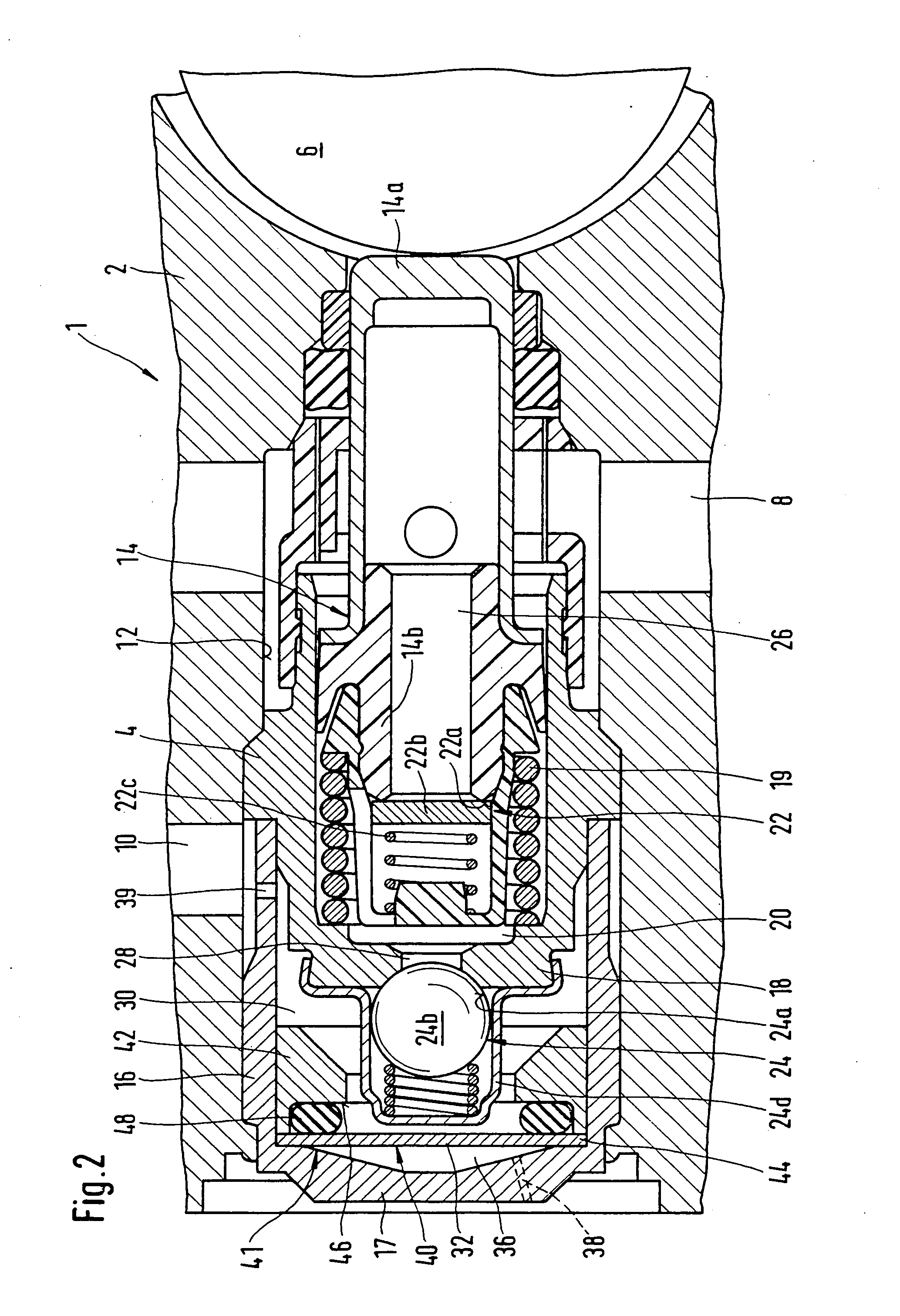
[0008] The pump assembly of the invention is intended in particular as a pump in a brake system of a vehicle and is used to control the pressure in wheel brake cylinders. Depending on the type of brake system, the abbreviations ABS (for anti-lock brake system), TCS (traction control system), VDC (vehicle dynamics control) and EHB (electrohydraulic brake system) are used for such brake systems. In the brake system, the pump serves for instance to return brake fluid from a wheel brake cylinder or a plurality of wheel brake cylinders to a master cylinder (ABS) and / or to pump brake fluid out of a supply container into a wheel brake cylinder or a plurality of wheel brake cylinders (TCS or VDC or EHB). In a brake system with wheel slip control (ABS or TCS) and / or a brake system serving as a steering aid (VDC) and / or an electrohydraulic brake system (EHB), for instance, the pump is needed. With wheel slip control (ABS or TCS), locking of the wheels of the vehicle during a braking event inv...


PUM


Abstract

In piston pumps for brake systems used until now, there were often noise problems, from pressure pulsations. In the piston pump for brake systems proposed here, a pulsation-smoothing device (40) that functions effectively well is provided in the region of the outlet valve (24). As a result, substantially less noise occurs, and the durability of the piston pump (1) is substantially better. The piston pump is used essentially in traction-controlled motor vehicle brake systems.

Description

PRIOR ART[0001] The invention relates to a piston pump as generically defined by the preamble to claim 1. The piston pump is intended particularly for a hydraulic traction-controlled vehicle brake system.[0002] German Published, Nonexamined Patent Application DE 42 26 646 A1 shows a hydraulic vehicle brake system with a pump, in which a pressure damper is provided downstream of an outlet check valve. For the pressure damper provided in the pressure line to have an adequate effect, the pressure damper must be made suitably large. Because of the pressure damper, the known vehicle brake system is relatively large as well, and increased production cost is necessary. Upon actuation of the brake pedal, some of the pressure medium positively displaced via the driver's foot is forced into the pressure damper. Because the pressure damper must be relatively large for an adequate effect, upon actuation of the brake pedal a relatively large quantity of pressure medium has to be positively displ...

Claims


Application Information

Patent Timeline
IPC IPC(8): B60T17/00B60T8/40F04B11/00F04B53/00
CPCB60T8/4031F04B11/0091F04B11/0016B60T8/4068
Inventor SCHMITT, EDGARALAZE, NORBERTSCHAEFER, ERNST-DIETEREGLE, MARCUSBRAUN, JOCHENECKSTEIN, URSULAZIMMERMANN, PETERDEBUSMANN, CHRISTIANDREYER, MANFRED
Owner ROBERT BOSCH GMBH
Why Eureka
Try Eureka